
The German Legend: How LZB Paved the Way for High-Speed Rail
LZB is the continuous train control system developed in Germany to allow trains to exceed the 160 km/h visual limit. Using a continuous cable loop laid between the rails, it brings signaling information directly into the driver’s cab.
⚡ In Brief
- LZB (Linienzugbeeinflussung — “Linear Train Influence”) is the German continuous cab signalling and ATP system that enabled safe operation at up to 280 km/h on the German InterCity Express network from 1991, using a conductor loop cable laid between the rails to provide bidirectional data communication between the train and a central LZB control centre.
- LZB was the first European railway system to provide continuous cab signalling with automatic speed enforcement — the driver no longer needed to read lineside signals to determine their authority, and the ATP system continuously supervised the braking curve to the next restriction point rather than only at discrete signal locations.
- The physical cable loop running between the rails — visible on LZB-equipped lines as a continuous conductor alongside the track — transmits speed limit, target distance, gradient, and brake curve data to the train at every point along its length, providing the “electronic horizon” that makes safe high-speed driving without visual signals possible.
- LZB entered commercial service in Germany in 1965 for speeds up to 160 km/h, was progressively upgraded to support 200 km/h (1974), 250 km/h (1988), and 280 km/h (1991, for the first Neubaustrecke high-speed lines), establishing the operational proof of concept that directly informed the development of ETCS.
- DB Netz has committed to replacing LZB with ETCS Level 2 across the German high-speed network, with migration proceeding corridor by corridor through the late 2020s — when complete, LZB will have operated safely for over 60 years and will take its place as the most successful national cab signalling system in European railway history before standardisation.
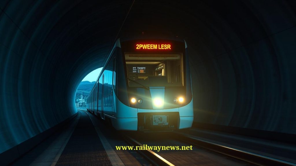
On 2 June 1991, the first Deutsche Bundesbahn ICE 1 high-speed train service departed Hamburg for Munich. The ICE reached 250 km/h on the new Hanover–Würzburg Neubaustrecke — a speed at which the lineside signals alongside the track flash past in under a second, entirely unreadable to a human driver. Yet the driver operated the train safely, maintaining precise speed compliance, braking smoothly for restrictions, and stopping at platforms to within centimetres of the intended position. No signal outside the window told them where their authority ended. The information was on their cab display, provided continuously by the cable running between the rails beneath the train — the LZB system.
LZB made the ICE possible. More broadly, it demonstrated to the European railway industry that continuous cab signalling and automatic speed enforcement was operationally viable on a busy mixed-traffic mainline network — not just a laboratory concept but a daily operational reality. The engineers who designed the ETCS specification in the 1990s built extensively on the operational lessons of LZB. Understanding LZB is understanding where European high-speed rail technology came from.
What Is LZB?
LZB (Linienzugbeeinflussung) is a continuous inductive train control system developed by Siemens for Deutsche Bundesbahn (DB) in the early 1960s. “Linienzugbeeinflussung” translates literally as “line train influence” — a characteristically German engineering portmanteau that describes the system’s defining feature: continuous influence over train movements along the entire line, rather than at discrete signal locations.
LZB is a cab signalling system (it transmits speed and authority information directly to the train’s cab display) and an ATP system (it automatically enforces braking compliance). Unlike the European AWS or PZB/Indusi systems of the same era — which were intermittent, providing information only when the train passed specific trackside devices — LZB provides a continuous data link between the moving train and the central LZB control office, updating the driver’s cab display many times per second as conditions change.
The LZB Cable Loop: How Continuous Communication Works
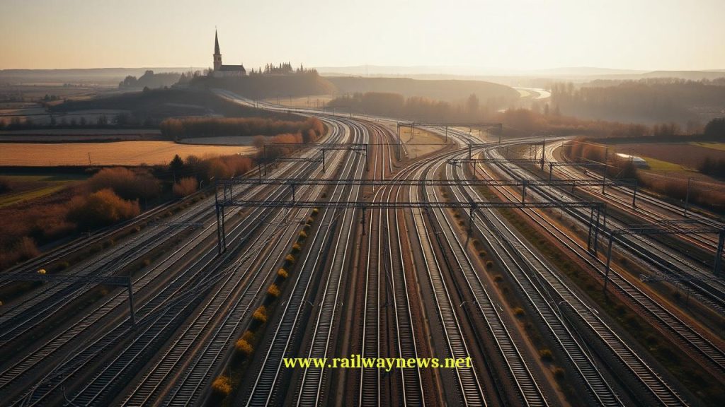
The most distinctive engineering feature of LZB is its transmission medium: a conductor loop cable laid between the rails along the entire LZB-equipped route. This is physically visible on LZB lines — a cable running down the centre of each track, secured to the sleepers or ballast between the two running rails, running continuously for the entire route length.
The loop works on inductive coupling principles similar to a transformer:
- The central LZB control office transmits a carrier signal (typically 36 kHz) into the loop conductor from one end.
- The train’s onboard LZB antenna — a receiver coil mounted under the vehicle, positioned above the loop — inductively couples with the conductor, receiving the modulated signal containing speed limit, target distance, gradient, and braking curve data.
- The communication is bidirectional: the train also transmits a return signal (at 56 kHz) back to the control office, carrying its position (reported via odometry) and identity.
- The control office thus has continuous knowledge of every train’s position and speed on the equipped section, and each train has continuous knowledge of its permitted speed and target distance.
The data update rate is rapid — typically 0.5–2 seconds — providing effectively continuous authority information rather than the discrete, location-based updates of balise systems. At 280 km/h, a train travels approximately 78 metres in one second — the LZB update interval of 0.5 seconds means the train’s authority is refreshed every 39 metres or less.
LZB Operational Capabilities
| Capability | LZB Specification | How Achieved |
|---|---|---|
| Maximum speed | 280 km/h (certified); 300 km/h tested | Continuous loop communication unaffected by speed; cab display replaces lineside signals |
| Electronic horizon | Up to 12 km ahead | Central office transmits speed and restriction data for route section ahead; train computer calculates braking curve to furthest restriction |
| Braking curve supervision | Continuous — intervention if curve exceeded | Onboard LZB computer compares actual speed to calculated curve; service or emergency brake commanded if exceeded |
| Headway at 250 km/h | ~4–5 minutes (blocked section approach) | Determined by braking distance at operating speed; LZB provides the braking curve; block section provides separation |
| Lineside signal requirement | Retained as fallback; not required for normal operation | Lineside signals provide fallback for non-LZB equipped trains; LZB trains operate on cab display at line speed |
| Position accuracy | Odometry with fixed reference points | Kilometre posts and known features provide absolute position fixes; odometry interpolates between fixes |
The LZB Cab Display: Germany’s First Digital Dashboard
The LZB cab display presented German high-speed drivers with information that no driver had previously received — a continuously updated picture of the track ahead with specific speed permissions, target distances, and braking curve guidance. The display showed:
- Actual speed: The train’s current speed from the odometry subsystem.
- Permitted speed (Sollgeschwindigkeit): The maximum speed the train is currently authorised to travel.
- Target speed (Zielgeschwindigkeit): The speed the train should be at the next restriction point — the driver should be braking toward this value.
- Target distance (Zielabstand): The distance to the next restriction point — how far ahead the target speed applies.
- Gradient indicator: Whether the track ahead is uphill or downhill, affecting braking distance.
This information structure is directly recognisable in the modern ETCS DMI — the “permitted speed,” “target speed,” and “target distance” concepts of ETCS correspond almost exactly to the equivalent LZB display fields. The ETCS DMI is, in significant respects, a standardised and modernised version of the information architecture LZB pioneered.
PZB: LZB’s Lower-Speed Companion
LZB was expensive to install and was deployed only on high-speed routes where its continuous supervision was operationally necessary. For the majority of the German conventional network — lines operating at up to 160 km/h — DB Netz uses PZB (Punktförmige Zugbeeinflussung — “Point Train Influence”), an intermittent ATP system that uses inductive magnets at specific trackside locations to transmit speed restriction and danger information to passing trains.
PZB operates at three frequency levels (500 Hz, 1000 Hz, 2000 Hz) corresponding to different speed restriction levels. When a train passes a PZB magnet, it receives an instruction that constrains its speed for a defined distance. The driver must acknowledge the instruction; failure to acknowledge triggers an emergency brake application. PZB provides safety backup for signal aspects but does not provide the continuous supervision that LZB offers — it is an intermittent system, and a driver who acknowledges a PZB restriction but then fails to brake is only caught if they exceed the monitored speed at a subsequent PZB location.
LZB-equipped trains carry both systems: LZB for high-speed continuous supervision on equipped sections, and PZB as the fallback system when LZB is not active (non-equipped sections, LZB equipment failure).
LZB vs ETCS: The Predecessor and Its Successor
| Parameter | LZB | ETCS Level 2 |
|---|---|---|
| Data transmission medium | Physical conductor loop cable in track | GSM-R / FRMCS radio (no trackside cable) |
| Position fixing | Odometry with fixed reference points at known locations | Eurobalise absolute fix + odometry between balises |
| Communication type | Bidirectional continuous inductive | Bidirectional radio; balise uplink for position fix |
| Maximum operational speed | 280 km/h (Germany ICE) | 350+ km/h (ETCS specification allows unlimited) |
| Interoperability | Germany, Austria, Spain (AVE); not cross-border compatible | Pan-European standard; same OBU for all ETCS networks |
| Trackside maintenance | High — continuous cable requires regular inspection and repair | Lower — only Eurobalises at key points; radio network shared with voice |
| Operational legacy | In service since 1965; proven 60-year safety record | Commercial service since late 1990s; proven on HSL networks |
| Future | Being replaced by ETCS; decommission target ~2030 | European standard for new deployments; progressive adoption |
LZB in Spain: ASFA and the AVE Connection
LZB was exported to Spain for the original Madrid–Seville AVE high-speed line, which opened in 1992 at 270 km/h. Spanish high-speed railways adopted the German system rather than developing a national alternative, and LZB (branded as LZB/AVE in the Spanish context) equipped the first generation of Renfe AVE lines. Spain’s broader conventional network uses ASFA (Anuncio de Señales y Frenado Automático), an intermittent ATP system broadly analogous to Germany’s PZB.
As Spain has expanded its high-speed network — now the longest in Europe by route-km — subsequent lines have progressively adopted ETCS Level 1 and Level 2, with the original LZB-equipped sections being upgraded as part of the wider ERTMS migration.
LZB’s Legacy: What ETCS Inherited
LZB’s most important contribution to European railway history is not its technology — the cable loop is obsolete — but its operational proof. When the European Commission began the ETCS specification process in the early 1990s, LZB provided the answer to a critical sceptical question: “Can continuous cab signalling and automatic speed enforcement work on a busy mixed-traffic network at high speed, in daily passenger service, reliably, over many years?” The answer, from 25 years of LZB operation on the German network, was an unambiguous yes.
Specific ETCS design elements that trace directly to LZB precedent include:
- The cab display information architecture — permitted speed, target speed, target distance — which ETCS standardised and extended from the LZB model.
- The continuous supervision philosophy — braking curve calculation and enforcement between signal locations, not only at signal faces — which was novel for European mainlines but proven by LZB.
- The concept of an “electronic horizon” — providing the driver with information about speed restrictions several kilometres ahead — which LZB implemented through its central control office model.
- The operational evidence that drivers could learn, trust, and operate safely using cab-only signalling without lineside signal references, which was genuinely uncertain before LZB’s deployment.
Editor’s Analysis
LZB’s place in railway history is secure: it was the first system to make truly continuous cab signalling and automatic ATP work reliably on a major European mainline, and it did so for sixty years with a safety record that fully justified the technology. But its obsolescence as ETCS replaces it is equally certain — the cable loop infrastructure, which made LZB’s continuous communication possible before wireless data networking existed, is now its greatest liability. Maintaining hundreds of kilometres of conductor cable buried in the track structure, subject to damage from tamping, maintenance work, flooding, and physical degradation, imposes maintenance costs and infrastructure inspection burdens that have no equivalent in the Eurobalise-and-radio architecture of ETCS. The DB Netz migration to ETCS is not a rejection of LZB’s operational philosophy — it is an upgrade of its physical implementation. Every ETCS Level 2 deployment inherits LZB’s core insight: continuous cab signalling works, continuous ATP supervision makes high-speed railways safer than discrete signal-based systems, and the driver’s interaction with a well-designed cab display can replace decades of lineside signal reading with something more reliable and more informative. The ICE 1 drivers who operated at 280 km/h on the Neubaustrecke in 1991, looking at their LZB cab displays rather than trackside signals, were operating in a mode that every ETCS-equipped driver operates in today. That continuity of operational philosophy, across sixty years and two generations of technology, is LZB’s real legacy. — Railway News Editorial
Frequently Asked Questions
- Q: Why is LZB being replaced by ETCS if it has worked safely for 60 years?
- LZB is being replaced for infrastructure and interoperability reasons, not safety reasons. The physical cable loop buried in the track requires significant ongoing maintenance — regular inspection, repair of cable damage from track work, and eventually wholesale replacement as the cable reaches end of life. The ETCS architecture (Eurobalises at fixed points, radio for continuous communication) has dramatically lower trackside maintenance requirements. Additionally, LZB is a German national system — an LZB-equipped locomotive cannot use its LZB capability when it crosses into France, Switzerland, or any other country. It must carry additional ATP equipment (PZB, TVM, TPWS, etc.) for each national system. ETCS provides a single onboard system that works across all European networks — the interoperability benefit alone would justify migration even if LZB were cheaper to maintain.
- Q: What is the difference between LZB and PZB?
- LZB and PZB are both German ATP systems made by Siemens, but they operate on completely different principles and serve different speed ranges. LZB (Linienzugbeeinflussung) is continuous — it uses a physical conductor loop running the entire length of the equipped track to provide constant bidirectional data communication between the train and a central control office. It supervises speed continuously against a calculated braking curve. It is used on high-speed routes where continuous supervision is required above 160 km/h. PZB (Punktförmige Zugbeeinflussung) is intermittent — it uses discrete inductive magnets at specific trackside locations to transmit speed restriction information only when a train passes those points. It monitors speed compliance at defined locations but not continuously between them. It is used on conventional speed lines up to 160 km/h. LZB-equipped trains carry both systems: LZB activates on LZB-equipped sections; PZB provides fallback protection on non-LZB sections and in LZB degraded mode.
- Q: How did LZB know where a train was before GPS existed?
- LZB used odometry combined with known reference points to determine train position — the same approach that ETCS uses today (with Eurobalises as the reference points instead). Each LZB-equipped locomotive carried a precise odometry system that counted wheel rotations and calculated distance travelled from the last known reference point. At defined locations along the route (typically every few kilometres), fixed “Referenzpunkt” markers provided an absolute position fix that corrected accumulated odometry error. The LZB central control office received each train’s odometry-derived position via the return signal on the conductor loop, allowing it to know each train’s position within approximately ±50 metres at any time. This was sufficient for the braking distances involved at LZB operating speeds — at 280 km/h, braking distances are measured in kilometres, so a 50-metre position uncertainty is an acceptable margin in the braking curve calculation.
- Q: Was LZB used anywhere other than Germany?
- Yes — LZB was deployed in three countries. In Germany (the primary market), it equipped all Neubaustrecken high-speed lines and major conventional routes where speeds exceeded 160 km/h. In Austria (ÖBB), LZB was deployed on upgraded main lines including the Western Railway (Westbahn) and Southern Railway (Südbahn). In Spain, LZB equipped the original AVE high-speed line between Madrid and Seville (opened 1992) — Spain adopted the German system for its first high-speed line before developing its national ASFA system and later adopting ETCS for subsequent lines. LZB was considered for other markets but the proprietary cable-loop infrastructure and the emergence of ETCS as a pan-European standard in the 1990s prevented wider adoption. The ETCS specification, which effectively made LZB obsolete for new deployments, was developed partly in response to the need to replace the proliferation of national systems like LZB with a single interoperable standard.
- Q: When will LZB be fully decommissioned?
- DB Netz’s ETCS deployment programme is progressively replacing LZB on the German high-speed and mainline network, with the migration proceeding corridor by corridor through the late 2020s. The Cologne–Frankfurt high-speed line was one of the first major ETCS Level 2 deployments in Germany (operational from 2002), effectively LZB-free from opening. Other corridors are being migrated as they undergo signalling renewals. The complete decommissioning of LZB across the German network is targeted for approximately 2030–2035, though given the scale of the migration programme and DB Netz’s infrastructure investment budget constraints, some corridors may retain LZB beyond that date. Austrian ÖBB’s LZB decommissioning timeline broadly parallels DB Netz’s. In Spain, LZB on the original AVE sections has largely been or is being replaced as part of the broader ETCS deployment on Renfe’s high-speed network.

Railway infrastructure, rolling stock and transport technologies specialist focused on global rail industry developments, high-speed rail systems, signaling technologies and freight transportation. Covering railway investments, public transport modernization, rail operations and international mobility projects across Europe, Asia and North America.
RELATED POSTS

August 1, 2026 7:56 am
BMZ delivered two new TEM18DM diesel shunting locos to RZD...
August 1, 2026 7:14 pm
€205 billion funding shortfall threatens the TEN-T rail network's completion...
August 1, 2026 7:11 pm
An Ipsos survey across 29 countries found that 33% of...
August 1, 2026 8:06 pm
European Commission approved a regulation on 9 July 2026 requiring...
August 1, 2026 3:17 pm
A UK firm since 2008 launched QR Shinkansen tickets for...
August 1, 2026 5:11 pm
Italo launched a Rolling Stones campaign on 1 July, running...