
Here are a few options, keeping in mind the “Click-Worthy but professional” and 75-character limit:**Option 1 (Focus on EU & Safety):** EU Rail Safety: How EN 15566 Ensures Cross-Border Compatibility**Option 2 (Focus on Interoperability):** EN 15566: The Standard Unifying Europe’s Rail Interoperability**Option 3 (More direct, highlights importance):** Essential For EU Rail: Understanding EN 15566’s Safety Impact**Option 4 (Short & punchy):** EN 15566: Europe’s Backbone For Rail Safety & InteroperabilityI think **Option 1** or **Option 4** are the strongest, as they clearly state the entity (EU/Europe), the standard, and the key benefits (safety, interoperability, compatibility).Let’s go with **Option 1** as it uses “How” which implies the article will explain, adding to click-worthiness.
Discover EN 15566: the vital standard ensuring railway safety, reliability, and seamless interoperability for draw gear and screw couplings across Europe.
“`html
Understanding EN 15566: The Standard for Railway Draw Gear and Screw Coupling
EN 15566 is a crucial European Standard that specifies the technical requirements for the design, manufacturing, testing, and supply of draw gear and screw coupling components for railway rolling stock. Its primary objective is to ensure mechanical interoperability, safety, and reliability for vehicles equipped with this conventional manual coupling system across the European railway network.
This standard forms the backbone of compatibility for a vast fleet of freight wagons, passenger coaches, and locomotives that rely on the screw coupling system. By defining precise dimensions, material properties, and performance criteria, EN 15566 guarantees that a component from one manufacturer can be safely and effectively coupled with that of another, which is fundamental for seamless cross-border rail operations.
Core Components Defined by EN 15566
The standard covers the entire assembly, which consists of several key interacting components. Each has a specific function and is subject to stringent requirements.
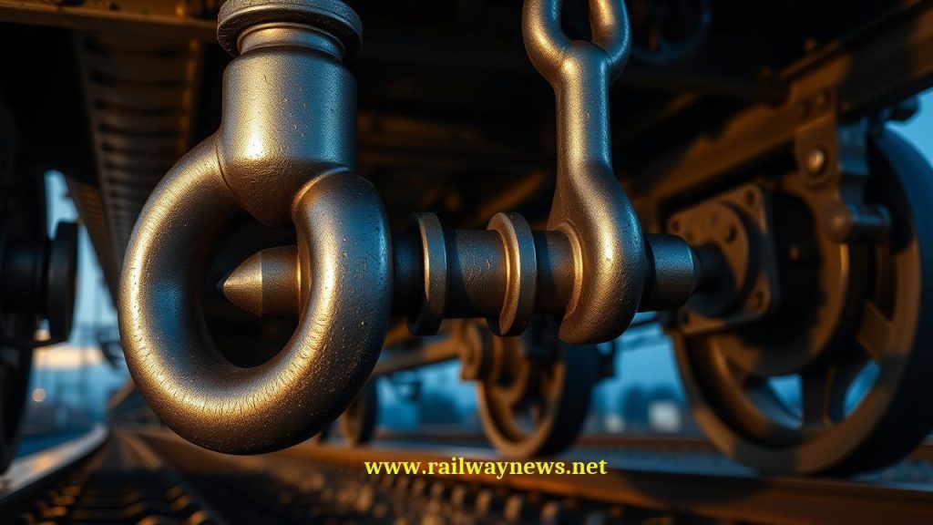
The Screw Coupling Assembly
This is the manually operated adjustable link between two vehicles. It allows for the tensioning of the connection, ensuring the buffers are pre-compressed and the train is coupled without slack.
- Coupling Link (Shackle): The large ‘D’ shaped loop that engages with the draw hook of the adjacent vehicle.
- Screw Spindle and Nut: The threaded bar and trunnion mechanism used to lengthen or shorten the coupling to connect or disconnect vehicles. A weighted lever is attached for manual operation.
- Coupling Body: The main structural element that connects the screw spindle to the coupling link.
The Draw Hook
The draw hook is the fixed, load-bearing point on the vehicle’s headstock to which the screw coupling is attached. It is designed to withstand the immense tensile forces generated during train operation, including traction and dynamic braking events.
The Draw Gear Assembly
The draw gear is the complete system behind the headstock that connects the draw hook to the vehicle’s underframe. Its critical function is not only to transmit traction forces but also to absorb and dissipate energy from longitudinal shocks.
- Draw Bar: The primary bar that connects the draw hook to the energy absorption elements and, ultimately, the vehicle frame.
- Energy Absorption Elements: These can be ringfeder friction springs, elastomer springs, or hydraulic units. They dampen shocks and jerks during train start-up, braking, and marshalling, protecting both the cargo and the vehicle structure.
Key Technical and Performance Requirements of EN 15566
The standard is highly technical, focusing on ensuring that all components can withstand the harsh operational environment of railway service. The core requirements can be broken down into several areas.
Material Specifications and Manufacturing
EN 15566 mandates the use of high-strength, fatigue-resistant steels. Components like draw hooks and coupling links are typically manufactured from micro-alloyed forged steel. The standard specifies requirements for:
- Chemical Composition: To ensure strength, weldability (where applicable), and resistance to brittle fracture at low temperatures.
- Mechanical Properties: Minimum values for yield strength, ultimate tensile strength, elongation, and impact toughness (Charpy V-notch test) are defined to guarantee performance under extreme loads and in cold climates.
- Manufacturing Processes: Forging and heat treatment processes are tightly controlled to achieve the desired grain structure and material properties, eliminating internal defects.
- Non-Destructive Testing (NDT): Critical components must undergo NDT methods like magnetic particle inspection (MPI) or ultrasonic testing (UT) to ensure they are free from surface or internal flaws.
Dimensional and Geometric Tolerances
To achieve universal interoperability, the standard defines a set of precise geometric dimensions and tolerances for all interfacing parts. This includes the jaw opening of the draw hook, the geometry of the coupling link, and the length of the screw coupling in its fully extended and retracted positions. This precision ensures any compliant coupling can connect to any compliant hook.
Mechanical Strength and Testing Protocols
This is the most critical aspect of the standard. Components must pass a series of rigorous type tests to prove their design and manufacturing quality. The main tests are:
| Test Type | Objective | Typical Procedure | Acceptance Criteria |
|---|---|---|---|
| Static Tensile Test | To verify the ultimate strength of the component and its behavior under extreme, non-recurring loads. | The component or assembly is subjected to a slowly increasing tensile force up to a specified proof load (e.g., 1,500 kN) and then to a breaking load. | No permanent deformation (yielding) must occur up to the proof load. The component must withstand the minimum breaking load without fracturing. |
| Fatigue (Dynamic) Test | To simulate the cumulative effect of millions of load cycles experienced during the service life of the component. | The component is subjected to a cyclic load of varying amplitude (e.g., +/- 300 kN) for a specified number of cycles (e.g., 2 million cycles). | The component must complete the required number of cycles without the initiation of fatigue cracks, which are checked for using NDT methods. |
| Assembly Test | To ensure the correct interaction and function of all parts within the screw coupling assembly. | The complete screw coupling is tested for proper operation, including ease of rotation of the screw spindle under load. | The coupling must function as intended throughout its range of adjustment without binding or excessive effort. |
Interoperability and Safety Implications
Compliance with EN 15566 is fundamental for the Technical Specifications for Interoperability (TSI), particularly for the ‘WAG’ (Wagons) and ‘LOC&PAS’ (Locomotives & Passenger) subsystems in the EU. A non-compliant component presents a significant safety risk, as a failure of a draw hook or coupling in service can lead to a train separation, a highly dangerous event that can cause derailment and collision. The standard’s rigorous testing regime is designed specifically to prevent such failures by addressing fatigue, ultimate strength, and material toughness.
Marking and Identification
To ensure traceability and verify compliance, every major component of the draw gear and screw coupling must be permanently marked. The markings typically include:
- Manufacturer’s name or mark
- Year of manufacture
- Serial number or batch code for traceability
- The number of the standard (EN 15566)
- Indication of the maximum static load
“`
RELATED POSTS

December 15, 2024 2:02 am
Discover EN 61375-3-2, the vital standard ensuring MVB device interoperability,...
December 15, 2024 2:02 am
EN 13260 is the cornerstone European standard for railway wheelsets....

September 22, 2023 1:10 pm
Safety first on the ballast. A technical guide to UIC...

September 30, 2023 2:16 am
Stowing the suitcase safely. A technical guide to UIC Leaflet...

September 22, 2023 11:31 am
UIC Leaflet 171 defines the standards for the exchange of...

September 23, 2023 4:47 pm
UIC Leaflet No: 966 – Chapter 9 – Information Technology,...