
What is Railway Coupler Types
Understanding railway couplers: The difference between Manual (Screw), Semi-Automatic (Janney/AAR), and Fully Automatic (Scharfenberg) coupling systems.

⚡ In Brief
- A railway coupler is the mechanical, pneumatic, and electrical interface between vehicles — it transmits traction and braking forces, carries compressed air for the brake system, and on modern stock transfers electrical power and data signals, all through a single connection point.
- Four main coupler systems dominate global freight and passenger operations: the European screw coupler with side buffers, the North American AAR knuckle coupler, the Scharfenberg automatic coupler, and the Russian SA-3 coupler — none of which are mutually compatible.
- Europe’s screw coupler requires a shunter to physically step between wagons to connect the hook-and-screw link and individual air hoses — a process taking 3–5 minutes per connection that is both labour-intensive and responsible for a significant proportion of shunting injuries.
- Digital Automatic Coupling (DAC) — the programme to replace Europe’s 500,000+ screw-coupled freight wagons with fully automatic couplers — is the largest single rolling stock upgrade programme in European railway history, with a planned migration window of 2026–2035.
- The Scharfenberg coupler, used on virtually all modern passenger EMUs, high-speed trains, and metros, connects mechanical link, brake pipe, and electrical contacts simultaneously in a single impact — enabling train splitting and joining at stations in under 60 seconds without any human intervention at the coupling face.
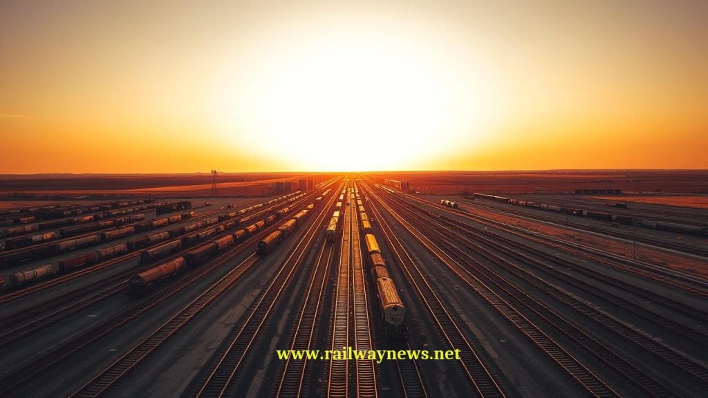
Every minute, across Europe’s freight network, a shunter steps between two wagons standing in a marshalling yard. The task is routine: lift the screw link from its stowage hook, drape it over the draw hook of the adjacent wagon, tighten the screw by hand until the buffers compress slightly, then crouch down to connect two rubber air hoses by feel. The whole operation takes about three minutes per coupling. Multiply that by the hundreds of thousands of couplings performed daily across European freight operations, and the result is a significant labour cost, a meaningful accident rate — shunting is among the most hazardous activities in railway operations — and a structural bottleneck in the efficiency of European freight.
This is the coupling problem that has defined European freight railways since the 1840s, and that the DAC programme now aims to finally solve. Understanding why different coupler systems exist, how they work, and why changing them is so difficult requires understanding the full technical and operational scope of what a railway coupler actually does.
What Does a Railway Coupler Do?
A railway coupler performs three distinct functions simultaneously:
Mechanical connection: Transmits tensile (draw) forces when the locomotive pulls the train, and compressive (buffer) forces when the train brakes or is pushed. On heavy freight trains, these forces can reach 1,500–2,500 kN in tension. The coupler must transmit these forces without failure through the full range of track curves and gradients the train will encounter.
Pneumatic connection: Connects the continuous brake pipe (and on modern stock, the main reservoir pipe) that runs the length of the train. The brake pipe carries compressed air that controls the train’s brakes — a break in the air pipe connection causes automatic emergency brake application across the entire train.
Electrical / data connection: On modern passenger and freight stock, the coupler also connects electrical lines carrying train bus data (control signals, diagnostic information, door status), low-voltage auxiliary power, and in some cases high-voltage traction power for multiple-unit operation. This electrical connection is what enables multiple units to operate as a single train under control from one cab.
The Four Main Coupler Systems Compared
| Coupler Type | Automation | Primary Region | Typical Use | Max Draw Force | Auto Air / Electric |
|---|---|---|---|---|---|
| Screw coupler (UIC) | Manual | Europe, UK, Middle East, parts of Asia | Freight wagons, older passenger coaches | ~850 kN | No — hoses connected manually |
| AAR knuckle (Janney) | Semi-automatic | North America, China, Australia, parts of South America | Heavy freight; some passenger | ~2,000–3,600 kN | No — hoses connected manually |
| Scharfenberg (Schaku) | Fully automatic | Global — passenger EMUs, metros, HSR | EMUs, metros, high-speed trains, light rail | ~1,000–1,500 kN | Yes — all connections simultaneous |
| SA-3 (Willison) | Semi-automatic | Russia, CIS countries, Baltic states (freight) | Heavy freight in cold-climate operations | ~2,500 kN | No — hoses connected manually |
| DAC (Digital Automatic Coupler) | Fully automatic | Europe (migration 2026–2035) | European freight wagons (replacing screw) | ~2,500 kN (target) | Yes — air + electric data simultaneous |
1. The Screw Coupler: Europe’s 180-Year-Old Standard
The UIC screw coupler — consisting of two side buffers and a central hook-and-screw chain link — has been the standard for European freight wagons since the 1840s. It was standardised by the International Union of Railways (UIC) and remains in use on approximately 500,000 freight wagons across the European network today.
The system works as follows: each wagon end has two side buffers (spring-loaded cylindrical pads) that absorb compressive forces between wagons, and a central draw hook from which the screw link hangs when not coupled. To couple two wagons, a shunter lifts the screw link from one wagon and places it over the draw hook of the adjacent wagon, then tightens the screw until the buffers make contact — taking up the slack. Air hoses must then be connected separately by hand.
The screw coupler’s critical disadvantage is that every coupling requires a person to physically enter the space between wagons — an inherently hazardous operation. European railway safety data consistently identifies shunting, including coupling operations, as one of the highest-risk activities in rail operations. Automation of this operation has been technically feasible for decades; the barrier to change has been the scale and cost of retrofitting the existing wagon fleet.
2. The AAR Knuckle Coupler: North America’s Heavy Haul Standard
The AAR (Association of American Railroads) knuckle coupler — also called the Janney coupler after its 1873 inventor Eli Janney — is a semi-automatic coupler used on virtually all freight rolling stock in North America, China, Australia, and much of South America. The coupler head features a rotating knuckle (shaped like a cupped hand) that opens to receive the opposing coupler and snaps locked when the two faces impact — the mechanical connection is automatic and requires no manual intervention.
However, the air hoses (brake pipe and main reservoir) must still be connected manually, making the AAR system semi-automatic rather than fully automatic. On North American freight trains, which may run to 100 wagons or more, the hose connection task is significant — but the mechanical coupling of the knuckle itself is safe, fast, and requires no person between the wagons.
The AAR coupler’s strength rating — up to 3,600 kN tensile force on heavy-haul versions — reflects the demands of North American heavy freight operations, where train weights of 10,000–20,000 tonnes are routine. European screw couplers, rated at approximately 850 kN, would be structurally inadequate for such loads.
3. The Scharfenberg Coupler: The Modern Passenger Standard
The Scharfenberg coupler (patented 1903, widely adopted from the 1950s onwards) is the standard fully automatic coupler for passenger EMUs, metro trains, high-speed trains, and light rail worldwide. The coupling head features a rigid conical protrusion (the cone) and a matching socket, surrounded by the mechanical locking mechanism. When two Scharfenberg-equipped vehicles approach each other at low speed, the cones guide the heads into alignment, the locking mechanism engages automatically, and — in a single impact — the mechanical draw/buffer connection, the pneumatic brake pipe connection, and the electrical contact block are all made simultaneously.
The result is that two train sets can be coupled completely, including all pneumatic and electrical connections, without any human intervention at the coupling face. A driver coupling two EMU sets at a terminus station needs only to drive one set into the other at walking speed — the Scharfenberg coupling completes the entire connection automatically. The reverse — uncoupling — is performed by remote command from the driver’s cab, releasing all connections simultaneously.
This capability enables operational patterns not possible with manual systems:
- Divide-and-join at intermediate stations: A train arrives as an eight-car formation, splits into two four-car sets at a junction station, each continuing to a different destination — all without shunting staff, in under 60 seconds at the platform.
- Multiple-unit operation: The electrical connection through the Scharfenberg coupler carries the train bus (typically UIC 568 or Ethernet-based), allowing the master cab to control traction, braking, and doors on all coupled units as a single train.
- GoA3/4 automated coupling: In driverless metro systems, train sets can be automatically coupled and decoupled under ATO control without any human involvement.
4. The SA-3 Coupler: Russia’s Cold-Climate Standard
The SA-3 coupler (also called the Willison coupler after its original designer) is the standard for freight rolling stock across Russia, the CIS countries, and the Baltic states. Like the AAR knuckle coupler, the SA-3 achieves automatic mechanical coupling on impact, with air hoses connected manually. The SA-3 is specifically designed for the extreme cold of Russian winters: the coupling mechanism uses larger tolerances and simpler geometry than the AAR system to remain functional at temperatures as low as −50°C, where lubricants freeze and metals contract significantly.
The SA-3/AAR incompatibility — the two systems cannot couple directly — creates an operational break point at the border between CIS and Western European freight operations, which already face a track gauge change (1,520 mm Russian gauge to 1,435 mm standard gauge). At gauge-change stations, wagons must be recoupled as well as having their bogies changed or adjusted.
DAC: Digital Automatic Coupling — Europe’s €10 Billion Migration
The most significant coupler development in European railway history is currently underway: the Digital Automatic Coupling (DAC) programme, managed by the European Commission and the International Union of Railways (UIC), aims to replace Europe’s entire freight wagon fleet with fully automatic couplers by 2035.
DAC is not simply a new coupling mechanism — it is a system transformation. The DAC coupler specified for European freight combines:
- Automatic mechanical coupling: Compatible with existing buffer geometry; couples on impact without manual intervention.
- Automatic pneumatic connection: Brake pipe and main reservoir pipe connect automatically — eliminating the need for manual hose connection entirely.
- Electrical data connection: A standardised data cable connection enabling Train Composition Detection (TCD) — the wagon knowing its position in the train, its load, its identity — and Condition Monitoring (brake status, bearing temperature, door status) transmitted from every wagon to the locomotive and to the network manager in real time.
| Parameter | Current (Screw Coupler) | DAC (Target) |
|---|---|---|
| Coupling time per wagon pair | 3–5 minutes (manual) | <30 seconds (automatic) |
| Staff required between wagons | Yes — shunter enters between wagons | No — fully automated |
| Air hose connection | Manual | Automatic |
| Wagon data connectivity | None | Digital train bus: position, load, brake status, bearing temp |
| Train formation automation | Not possible | Automatic train composition detection; supports robotic shunting |
| Estimated migration cost | — | ~€10–15 billion across European freight wagon fleet |
The DAC migration faces the challenge that all freight wagons on a route must use the same coupler type — a mixed fleet of screw-coupled and DAC-equipped wagons cannot operate in the same train without adapter plates. This means the migration cannot be gradual wagon-by-wagon: it requires a coordinated, country-by-country or corridor-by-corridor cutover. The European Commission’s preferred approach is a “Big Bang” migration corridor by corridor, with financial support to wagon owners for retrofitting costs, targeting completion by 2035.
Coupler Compatibility: Why They Cannot Be Mixed
Different coupler systems are fundamentally incompatible because they differ in head geometry, coupling mechanism, buffer geometry, draw hook height, and pneumatic/electrical interface. A screw coupler wagon and an AAR knuckle wagon cannot be directly coupled — the draw hooks and buffer faces do not physically mate, and even if they did, the pneumatic interfaces are different.
For rescue operations — when a locomotive of one coupler type must recover a failed train of another — adaptation equipment is used:
- Barrier wagons: A specially equipped wagon with one coupler type at each end, inserted between the incompatible vehicles.
- Coupler adapters: Clip-on mechanical adapters that fit over one coupler head to present a compatible face to the other system. These are used for rescue only at low speed — they are not approved for normal service operation.
- Transition locomotives: Some locomotives on international freight corridors are equipped with interchangeable coupler heads to operate with wagons of either the screw or SA-3 system.
Editor’s Analysis
The DAC migration is the most consequential infrastructure decision in European freight rail since the adoption of ETCS, and it is arguably more technically complex — ETCS replaces signalling equipment installed in depots and alongside track, while DAC requires modifying or replacing every single freight wagon in the European fleet. The economic case is clear and has been established by multiple independent studies: the labour cost savings from eliminating manual coupling, the accident reduction from removing shunters from between wagons, and the operational efficiency gains from automated train composition detection collectively justify the migration cost over a 10–15 year payback period. The strategic case is even stronger: a digitally connected freight wagon fleet — where every wagon’s position, brake status, bearing temperature, and load are visible in real time — is the foundation of the autonomous freight railway that operators are planning for the 2030s. Without DAC, that future is unreachable regardless of how sophisticated the locomotive and signalling technology becomes. The wagons are the missing link. The question is not whether Europe should migrate to DAC — the case is made — but whether the governance and funding mechanisms can deliver a coordinated migration of half a million wagons across 26 countries within a decade. That is a project management challenge of extraordinary complexity, and the history of European railway standardisation projects suggests caution about whether timelines will hold. — Railway News Editorial
Frequently Asked Questions
- Q: Why has Europe kept the screw coupler for so long when better options exist?
- The screw coupler has persisted for 180 years because of the network effect: every wagon and every locomotive in Europe is built to the same screw coupler standard, and they are all mutually compatible. Changing the standard requires changing every wagon simultaneously — a half-migrated fleet is worse than no migration, because screw-coupled and DAC-equipped wagons cannot operate in the same train without adapter plates. The cost and coordination required to replace 500,000+ wagons across 26 countries has repeatedly defeated previous migration attempts. The current DAC programme is the most serious and best-funded attempt yet, backed by European Commission mandate and co-funding, but it still represents the largest coordinated rolling stock retrofit programme in European railway history.
- Q: Can a Scharfenberg coupler handle the forces of heavy freight trains?
- Standard Scharfenberg couplers used on passenger EMUs are rated for approximately 1,000–1,500 kN — adequate for passenger trains but insufficient for heavy freight trains, which can require 2,000–3,600 kN capacity. Heavy-duty Scharfenberg variants exist for freight applications, but the Scharfenberg design philosophy — optimised for rapid automatic coupling and uncoupling at passenger service frequency — is less suited to the infrequent but very high-force demands of heavy freight. The DAC coupler being developed for European freight is a distinct design that combines automatic coupling capability with the higher force ratings required for freight operations, rather than being a direct adaptation of the Scharfenberg passenger coupler.
- Q: What is “train bus” and why does it need to run through the coupler?
- The train bus is the digital communication network that runs the length of a train, connecting the master control system in the leading cab to every traction, braking, door, and auxiliary system in every vehicle. On a modern EMU, the train bus carries the commands that enable multiple units to operate as a single train — the driver presses the brake pedal once and all bogies on all vehicles brake proportionally; the driver closes the doors and all doors on all vehicles close simultaneously. The train bus cables run through the electrical contacts in the Scharfenberg coupler between vehicles. If the coupler’s electrical contacts fail to connect properly, the multiple units cannot communicate — they cannot operate in multiple-unit mode. This is why the simultaneous and reliable connection of electrical contacts is as important as the mechanical locking in modern automatic couplers.
- Q: What happens to the coupler in a collision — does it help protect passengers?
- Modern railway couplers and the vehicle end structures they connect are designed as a crash energy management system. Scharfenberg couplers on passenger trains typically incorporate two or three stages of energy absorption: first, the coupler itself deforms plastically at a defined force level (typically 800–1,000 kN), absorbing collision energy; second, anti-climber devices prevent one vehicle from overriding another vertically (a major cause of fatalities in historical collisions); third, the vehicle end structure crumple zones absorb remaining energy. This “controlled collapse” approach, defined in EN 15227 (Crashworthiness of railway vehicles), means that in a collision at moderate speed, the coupler and end structure absorb the energy in a controlled manner that protects the passenger compartment. The screw coupler with side buffers also provides crash energy absorption through buffer compression, but without the anti-climber and integrated energy management of modern Scharfenberg systems.
- Q: What is the difference between draw force and buffer force in a railway coupler?
- Draw force (tensile force) is the pulling force the coupler transmits when the locomotive accelerates and pulls the train. On a 1,000-tonne freight train accelerating at 0.1 m/s², the maximum draw force in the first coupler behind the locomotive is approximately 100 kN — but in-train dynamics (wagon mass and slack) can create dynamic surges several times higher during acceleration transients. Buffer force (compressive force) is the pushing force transmitted when the train brakes or is propelled. In the screw coupler system, compressive forces are taken by the side buffers; in the AAR and DAC systems, both tensile and compressive forces are transmitted through the central coupler head. The reason European wagons have both side buffers and a central coupling (rather than a single central coupler like the AAR system) is historical: the side buffer arrangement was standardised before central-coupler systems were well-developed, and changing it requires changing not just the coupler but the entire end structure of every wagon.

Railway infrastructure, rolling stock and transport technologies specialist focused on global rail industry developments, high-speed rail systems, signaling technologies and freight transportation. Covering railway investments, public transport modernization, rail operations and international mobility projects across Europe, Asia and North America.
BENZER KONULAR
July 4, 2026 11:41 pm
Eurostar cancelled all direct London–Amsterdam trains through July 2 after...
July 1, 2026 1:37 pm
NRHS awarded $187K to 34 U.S. rail heritage projects in...
July 1, 2026 1:42 am
UK government launched a £30bn Better Connected plan, allocating £15.6bn...
July 1, 2026 6:37 am
Amtrak launched a small-plate dining program for Acela First Class...
July 1, 2026 8:49 am
The Short Line Training Center launched FRA-funded online DSLE and...
July 4, 2026 11:02 pm
Eurostar suspends all direct London–Dutch trains through 2 July after...