
What is a Traction Substation? Powering the Railway Network
Traction substations are entering a period of significant technological change driven by two forces: the energy transition and the digitalisation of power systems.
⚡ In Brief
- A Traction Power Substation (TPSS) converts high-voltage grid electricity to the voltage and current type required by electric trains — stepping down from 132 kV or 33 kV grid supply to 25 kV AC for mainlines or 750 V DC for metro systems.
- AC substations on mainlines are spaced 20–50 km apart; DC substations on metro systems are spaced 1–3 km apart, reflecting the fundamental difference in how AC and DC power propagates along a wire.
- A single high-speed mainline substation can deliver 20–60 MVA of power — enough to simultaneously accelerate several high-speed trains from standstill.
- Regenerative braking returns energy from decelerating trains back through the substation to the grid or to adjacent accelerating trains, with modern systems recovering 15–30% of total traction energy consumption.
- Traction substations account for approximately 20–30% of the total capital cost of an electrification project, making them one of the largest single infrastructure investment categories in railway electrification.
At 7:58 on a Monday morning, a busy metro network faces simultaneous acceleration of dozens of trains across the city. In the space of a few minutes, the network draws hundreds of megawatts of power from the grid — a demand spike equivalent to a small city suddenly switching on every appliance simultaneously. Managing that demand, delivering the right voltage to every train across hundreds of kilometres of wire, and feeding recovered energy from braking trains back into the system — all in real time, automatically, with no single point of failure — is the job of the traction power substation network.
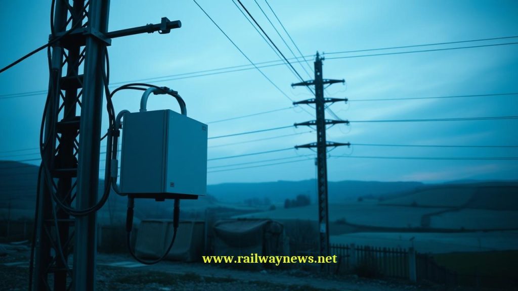
Traction substations are the invisible infrastructure of electric rail. Hidden in trackside buildings, they are rarely mentioned in railway coverage, yet without them every electric train on Earth stops moving. Understanding how they work explains both the economics of railway electrification and the engineering challenges of decarbonising rail.
What Is a Traction Power Substation?
A Traction Power Substation (TPSS) is an electrical facility that takes power from the national transmission or distribution grid and converts it to the voltage, current type, and quality required to supply electric trains. The conversion involves two primary processes:
Voltage transformation: The grid delivers power at transmission voltages (typically 110–400 kV) or distribution voltages (11–33 kV) that are too high for direct supply to railway equipment. Traction transformers step this down to the traction voltage — 25 kV AC for mainlines, or an intermediate AC voltage that is then rectified to 750 V DC for metro systems.
Rectification (DC systems only): Metro and tram systems typically operate on DC supply. The substation’s rectifier bank converts the AC supply from the transformer to DC at the required voltage (600 V, 750 V, or 1,500 V depending on the system). Modern rectifiers use silicon diode or thyristor technology, with active front-end rectifiers increasingly used to enable energy regeneration back to the grid.
Key Components of a Traction Substation
| Component | Function | Notes |
|---|---|---|
| Traction transformer | Steps down grid voltage to traction voltage | Oil-cooled; rating 5–60 MVA depending on line type |
| Rectifier (DC systems) | Converts AC to DC at traction voltage | Silicon diode or thyristor; 12-pulse or 24-pulse to reduce harmonics |
| Circuit breakers | Protect equipment from overloads and short circuits | Must interrupt very high fault currents within milliseconds |
| Busbars | Conduct and distribute power within the substation | Copper or aluminium; rated for full fault current |
| Feeder cables | Carry traction power from substation to OLE or third rail | High-voltage cables running trackside to feed points |
| Sectioning equipment | Divides OLE into electrically isolated sections | Allows maintenance isolation without de-energising entire line |
| SCADA / control system | Remote monitoring and control | Allows unmanned operation; connects to central energy management |
| Earthing system | Safety earth for personnel and equipment protection | Also manages return current and stray current control |
AC vs DC Substations: Full Comparison
| Parameter | DC Substation (Metro / Tram) | AC Substation (Mainline / HSR) |
|---|---|---|
| Output voltage | 600 V, 750 V, or 1,500 V DC | 15 kV or 25 kV AC |
| Key conversion | Transformer + Rectifier (AC → DC) | Transformer only (AC → AC, lower voltage) |
| Spacing | 1–3 km | 20–50 km |
| Typical rating | 1–4 MVA | 10–60 MVA |
| Grid connection voltage | 11–33 kV (distribution) | 33–132 kV (sub-transmission) |
| Regeneration to grid | Possible with active front end; absorbed by adjacent trains | Natural (AC inverters return energy to grid directly) |
| Stray current risk | High — DC leaks from running rails, corrodes buried metalwork | Low — AC stray currents are lower magnitude |
| Typical application | Metro, tram, urban rail, commuter networks | Intercity, HSR, mainline freight-capable routes |
Why DC Substations Are So Much Closer Together
The fundamental reason DC substations must be spaced much more closely than AC substations is the relationship between voltage, current, and power loss. Power (watts) equals voltage (volts) multiplied by current (amperes). To deliver the same power at lower voltage requires proportionally higher current. Higher current means greater resistive losses in the wire — losses proportional to the square of the current.
At 750 V DC, delivering 2 MW to a train requires approximately 2,667 amperes of current. At 25 kV AC, delivering the same 2 MW requires only 80 amperes. The resistive losses in the contact wire are proportional to current squared — so the 750 V system suffers losses approximately 1,100 times greater than the 25 kV system for the same power delivery over the same wire length. This is why DC systems need substations every 1–3 km: beyond that distance, the voltage drop in the wire is so large that trains cannot receive adequate power.
Auto-Transformer Substations: Extending AC Reach
On 25 kV AC mainlines, the basic single-feed system supplies 25 kV between the contact wire and the return rail. As trains draw current, voltage drops along the wire between substations. On long inter-substation sections or under heavy traffic, this voltage drop can reduce train performance.
The 2×25 kV auto-transformer system addresses this by introducing a second wire (the feeder wire) running at -25 kV relative to earth (i.e., 50 kV between contact wire and feeder wire). Auto-transformer stations placed every 10–15 km balance the voltage between the two wires, effectively doubling the voltage gradient over which power can be transmitted while halving the current in the rails — reducing resistive losses and stray current problems significantly. This system is used on all modern European high-speed lines and on the UK’s 25 kV AC electrification.
Regenerative Braking: Turning Kinetic Energy into Grid Power
When an electric train brakes, its traction motors operate as generators — converting the train’s kinetic energy into electrical energy rather than heat. This regenerated energy must go somewhere:
On DC systems: The regenerated energy flows back into the DC busbar. If another train is accelerating nearby on the same section, it absorbs this energy directly — the most efficient scenario. If no train is available to absorb the energy, the voltage on the DC busbar rises. If it rises above the maximum safe level, the braking train must switch to resistor braking (dissipating energy as heat) or the substation must absorb the energy using a reversible rectifier or energy storage system.
On AC systems: Modern four-quadrant converters (4QC) in AC trains can naturally return regenerated energy to the 25 kV system, which in turn feeds it back to the grid through the substation transformer. AC systems have an inherent advantage for regeneration because the AC grid can absorb unlimited regenerated energy without voltage issues.
Energy recovery rates on modern systems:
| System Type | Typical Regeneration Rate | Key Factor |
|---|---|---|
| Dense metro (many trains, high frequency) | 20–35% | High probability of adjacent accelerating train to absorb energy |
| 25 kV AC mainline | 15–25% | Direct grid return via 4QC converters |
| High-speed line (few stops) | 10–18% | Fewer braking events; long cruising sections |
Wayside Energy Storage: Capturing What Regeneration Misses
On DC metro systems, regenerated energy that cannot be absorbed by an adjacent train was historically wasted as heat in braking resistors. Wayside Energy Storage Systems (WESS) — supercapacitor banks or lithium-ion battery arrays installed at substations — address this by storing the excess regenerated energy and releasing it during the next acceleration event.
Deployments to date include:
- Madrid Metro: Supercapacitor WESS at multiple stations, achieving 30% reduction in energy consumption at equipped stations.
- Paris RER: Battery storage at substations tested on the RER B line, recovering braking energy during off-peak periods when fewer trains are present to absorb it.
- Lisbon Metro: Active inverter substations that return regenerated DC energy to the AC grid during periods of low traffic, converting what would be wasted heat into revenue-generating grid supply.
Substation Reliability and N-1 Redundancy
A failed traction substation can strand all trains in its feed section — potentially dozens of vehicles carrying thousands of passengers. Railway traction power systems are therefore designed to the N-1 standard: the loss of any single substation must not interrupt train service, because adjacent substations can extend their feed zones to cover the failed section.
This requires substations to have reserve capacity — they are not operated at their maximum rating under normal conditions, but at 60–70% capacity, leaving headroom to absorb the additional load from an adjacent failed substation. The OLE section switches that isolate each feed section can be remotely operated by the control centre to reconfigure the network around the failure within minutes.
Editor’s Analysis
Traction substations are entering a period of significant technological change driven by two forces: the energy transition and the digitalisation of power systems. On the energy side, the shift to renewable electricity generation creates new challenges for traction power systems — solar and wind generation is intermittent and geographically concentrated, while railway traction demand is predictable but highly peaked. The ability of railway traction systems to participate in grid demand response — absorbing surplus renewable generation during off-peak periods and releasing stored energy during peak demand — is increasingly recognised as a valuable grid service that railways could monetise. Several European network operators are exploring contracts to provide grid balancing services using their traction power infrastructure. On the digital side, the transition from manually-operated substations to fully automated, remotely-monitored SCADA-controlled facilities is largely complete on new installations. The frontier is predictive maintenance: using current, voltage, and temperature sensor data to predict transformer failures and rectifier degradation before they cause service disruptions. A traction substation transformer failure is a multi-day service disruption event — the transformer is large, heavy, and not always available as a spare. Condition monitoring that gives weeks rather than hours of warning of impending failure is worth considerably more than its installation cost on any busy line. — Railway News Editorial
Frequently Asked Questions
- Q: Why do railway systems use such high voltages?
- High voltage is used to minimise resistive power losses in the contact wire. Power loss in a wire equals current squared multiplied by resistance. For a given power delivery, higher voltage means lower current, and lower current means dramatically lower losses. A 25 kV AC system delivers the same power as a 750 V DC system at approximately 1/1,000th of the current, and therefore 1/1,000,000th of the resistive losses per unit of wire length. This is why high-speed lines use 25 kV AC and can place substations 40–50 km apart, while metro systems at 750 V DC need substations every 1–2 km.
- Q: What happens when a traction substation fails?
- On a properly designed railway, a single substation failure should not stop trains — adjacent substations are designed with sufficient reserve capacity to extend their feed zones and cover the failed section. The control centre reconfigures the OLE section switches remotely to connect the affected section to the adjacent substations’ feed. Trains in the affected section may experience reduced acceleration performance (as the voltage is slightly lower at the extremes of the extended feed zone), but service should continue. Only if multiple adjacent substations fail simultaneously — or if the failure occurs at an extreme point of the network with no adjacent substation to draw from — would trains be stranded.
- Q: How much does a traction substation cost?
- Costs vary significantly by voltage, rating, and location. A small DC metro substation (1–2 MVA, 750 V) in a standard building typically costs €1–3 million including civil works. A large 25 kV AC mainline substation (20–40 MVA) costs €5–15 million. High-speed line substations with auto-transformer equipment and full SCADA integration can reach €20–30 million. On a 300 km electrification project requiring perhaps eight 25 kV substations, the substation cost alone can represent €60–120 million — typically 20–30% of total electrification project cost.
- Q: Can railway substations export energy back to the grid?
- Yes, and this is increasingly common. On 25 kV AC systems, trains with modern four-quadrant converter technology naturally return regenerated braking energy to the AC system, which flows back to the grid through the substation transformer. On DC systems, “reversible substations” with active front-end technology can convert surplus DC energy (from regenerating trains) back to AC and export it to the grid. This capability is being actively developed as a grid balancing service — railways have large, predictable energy flows and substation infrastructure already connected to the grid, making them natural participants in demand response and energy storage programmes.
- Q: What is a switching post and how does it differ from a substation?
- A switching post (or sectioning post) is a trackside facility that contains OLE section switches and circuit breakers, but no transformer or rectifier — it does not generate or convert power. Its function is to divide the OLE into manageable electrical sections that can be isolated for maintenance or fault clearance, and to allow the control centre to reconfigure which substation feeds which section of track. Switching posts are typically much smaller and cheaper than substations and are placed between substations to provide finer-grained control of the traction power network.

Railway infrastructure, rolling stock and transport technologies specialist focused on global rail industry developments, high-speed rail systems, signaling technologies and freight transportation. Covering railway investments, public transport modernization, rail operations and international mobility projects across Europe, Asia and North America.
RELATED POSTS
July 1, 2026 1:42 am
UK government launched a £30bn Better Connected plan, allocating £15.6bn...