
What is a Catenary System? Overhead Line Equipment (OLE) Explained
The catenary system is at the centre of one of the most significant debates in railway policy: whether to continue investing in fixed electrification infrastructure or to allow battery and hydrogen traction to make OLE unnecessary on some routes.
⚡ In Brief
- A catenary system (Overhead Line Equipment / OLE, or Overhead Contact System / OCS) is the infrastructure that delivers electrical power to trains via an overhead wire touched by the train’s pantograph.
- The contact wire does not hang freely — it is held geometrically horizontal by droppers connecting it to a messenger wire above, ensuring consistent pantograph contact at all speeds.
- The contact wire is deliberately zigzagged laterally (staggered ±200–300 mm) rather than running in a straight line, distributing wear evenly across the width of the pantograph carbon strip.
- High-speed catenary (above 250 km/h) requires system tension of 27–31 kN and precise geometric tolerances to prevent pantograph bounce and loss of contact — a phenomenon called contact wire uplift.
- OLE installation costs €500,000–€2 million per track-kilometre depending on mast type, voltage, and design speed, making electrification one of the largest capital items in railway infrastructure programmes.
At 574.8 km/h — the world rail speed record, set by a French TGV in 2007 — a pantograph is sliding along a contact wire at 160 metres per second. At that speed, the pantograph head contacts and leaves each support point in less than 20 milliseconds. The wire must be perfectly tensioned, perfectly positioned, and perfectly maintained to stay in continuous electrical contact with the pantograph. A single loss of contact at that speed — a fraction of a second of separation — causes an arc that can burn through the contact wire or destroy the pantograph in an instant.
No one runs scheduled services at 574 km/h. But the engineering principles that make the TGV speed record possible are the same ones that govern every electrified railway in the world — from a 25 km/h metro system to a 350 km/h high-speed line. The catenary system is the invisible infrastructure that makes electric rail possible, and understanding how it works explains why electrification projects cost what they cost and take as long as they take.
What Is a Catenary System?
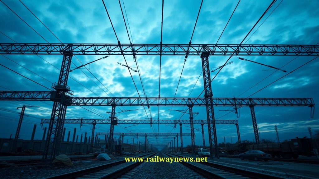
A catenary system is the complete assembly of wires, supports, and associated equipment that delivers electrical power from the traction substation to a moving train. The train draws current through its pantograph — a spring-loaded or pneumatically actuated current collector mounted on the roof — which slides along the underside of the contact wire. The current flows through the traction motors and returns to the substation via the running rails.
The word “catenary” comes from the Latin catena (chain) and describes the mathematical curve that a perfectly flexible chain or rope makes when hanging freely between two supports under its own weight. In a catenary system, the upper messenger wire hangs in this natural catenary curve between masts. The contact wire below it is held horizontal — not in a catenary curve — by droppers of varying length that connect the two wires at regular intervals.
Key Components of an OLE System
| Component | Function | Material / Notes |
|---|---|---|
| Contact wire | Direct electrical contact with pantograph | Hard-drawn copper or copper-silver alloy; grooved profile for dropper clamps |
| Messenger wire (catenary wire) | Supports contact wire via droppers; carries tension | Copper, bronze, or steel; hangs in natural catenary curve between masts |
| Droppers | Connect messenger wire to contact wire; maintain contact wire geometry | Short copper or steel wires; varying lengths to keep contact wire horizontal |
| Registration arms | Hold contact wire at the correct lateral position (stagger) at each mast | Insulated arms; set stagger angle at each support point |
| Masts / poles | Structural support for the entire system | Steel or concrete; spaced 50–70 m on standard lines, 65–80 m on HSR |
| Stitch wire | Reduces uplift at support points on high-speed lines | Additional wire between messenger wire and contact wire near masts |
| Tensioning equipment | Maintains constant wire tension despite temperature changes | Dead-end tensioning weights or automatic tensioners at section ends |
| Section insulators | Electrically isolate adjacent feed sections | Allow maintenance isolation without de-energising entire line |
The Stagger: Why the Wire Zigzags
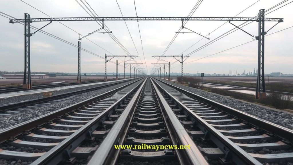
Looking along an electrified railway, the contact wire does not run in a straight line directly above the track centreline. It zigzags laterally — typically ±200–300 mm either side of the pantograph centreline — in a pattern that repeats every two or three mast spans. This is called stagger (or registration offset).
The purpose is wear distribution. A pantograph head is typically 1,450–1,950 mm wide, carrying a carbon strip that makes electrical contact with the wire. If the contact wire ran in a perfectly straight line, it would always contact the same narrow band on the carbon strip, wearing a groove into it rapidly. The stagger ensures that as the train travels, the contact point moves progressively across the full width of the pantograph head, distributing wear evenly and significantly extending the life of both the carbon strip and the contact wire.
At each mast, the registration arm positions the contact wire at its stagger offset. The wire then runs in a straight line to the next mast, where it is registered at the opposite offset. From above, the wire traces a gentle zigzag along the entire route.
OLE Voltage Systems: A Global Comparison
| System | Voltage | Current Type | Substation Spacing | Primary Users |
|---|---|---|---|---|
| 25 kV AC 50 Hz | 25,000 V | AC | 20–50 km | All modern HSR, UK mainline, France, Spain, China, India |
| 15 kV AC 16.7 Hz | 15,000 V | AC | 30–60 km | Germany, Austria, Switzerland, Norway, Sweden |
| 3 kV DC | 3,000 V | DC | 3–8 km | Italy, Belgium, Poland, Czech Republic, Russia (some lines) |
| 1.5 kV DC | 1,500 V | DC | 2–5 km | France (legacy), Netherlands, Japan (Shinkansen: no), Australia |
| 25 kV AC 60 Hz | 25,000 V | AC | 20–50 km | USA (Amtrak NEC), South Korea, Taiwan |
Flexible vs Rigid Catenary: Full Comparison
| Parameter | Flexible Catenary (Conventional) | Rigid Catenary (Conductor Rail / OCR) |
|---|---|---|
| Structure | Contact wire + messenger wire + droppers, under tension | Aluminium extrusion profile with copper contact insert, bolted to supports |
| Primary use case | Open line, high-speed rail, most mainline applications | Tunnels, metros, areas with very restricted vertical clearance |
| Maximum speed | 350+ km/h (with compound catenary and high tension) | Typically 160–250 km/h (limited by pantograph dynamics) |
| Installation height saving | Requires ~800–1,200 mm for wire system above contact wire | ~200 mm above contact surface — critical for tight tunnels |
| Maintenance requirement | Regular tension inspection, dropper replacement, wire wear monitoring | Low — copper insert replacement every 20–30 years |
| Ice/wind vulnerability | Moderate — requires tensioning system; ice can cause sag | Not applicable in tunnels; exposed versions vulnerable in severe cold |
| Examples | All HSR, UK 25 kV AC OHL, German Fahrdraht | Channel Tunnel, London Underground OHL sections, many metro systems |
High-Speed Catenary: The Engineering Challenge Above 250 km/h
Above 250 km/h, the dynamics of pantograph-catenary interaction become the dominant engineering constraint. As a pantograph approaches a support point, it must push the contact wire upward (uplift) and then return to the nominal height as it passes. At high speed, this creates a wave that propagates along the wire ahead of the pantograph.
If the pantograph travels faster than this wave — the wave propagation speed of the catenary — the pantograph catches its own wave, causing violent contact force fluctuations and loss of contact. The wave propagation speed of a tensioned wire is proportional to the square root of tension divided by linear mass. To push this speed above 350 km/h (the operating ceiling of current high-speed systems), catenary designers use:
- High tension: Modern HSR catenary uses 27–31 kN contact wire tension, compared to 10–15 kN on conventional lines. Higher tension = faster wave propagation = higher safe operating speed.
- Compound catenary: An additional auxiliary catenary wire between the messenger and contact wires, further stiffening the system and reducing uplift at support points.
- Reduced dropper spacing: Shorter intervals between droppers reduce the amplitude of wire oscillation between supports.
- Longer mast spans: Counter-intuitively, longer spans reduce the number of support point disturbances per km, improving contact regularity.
- Stitch wires: Short wires near each support that pre-load the contact wire upward, compensating for the increased stiffness at the support point.
Contact Wire Wear and Replacement
The contact wire wears continuously as pantographs slide along it. Modern contact wires have a cross-section of approximately 120–150 mm² and are replaced when worn down to 70–80% of their original cross-section — typically after 15–30 years on mainline routes, or 5–10 years on very high-frequency urban lines.
Wire wear is monitored by specialist overhead line inspection vehicles that use laser measurement or contact systems to measure the remaining cross-section at every point along the wire, producing wear profiles that identify sections approaching replacement threshold. On high-speed lines, some operators use automated optical systems mounted on revenue trains to monitor wire geometry and wear continuously in service.
OLE Installation Cost: Why Electrification Is Expensive
| Line Type | OLE Cost per Track-km | Key Cost Drivers |
|---|---|---|
| Standard mainline (25 kV AC) | €500,000–€900,000 | Mast foundations, wire, civil works |
| Urban / constrained (bridge works) | €1.0–€2.5 million | Bridge raising/modification, limited access, traffic management |
| High-speed line (new build) | €800,000–€1.5 million | High-tension compound catenary, wider mast spacing, traction substations |
| Tunnel (rigid catenary) | €300,000–€600,000 | Lower civil cost but specialist installation in confined space |
The biggest single cost item in many electrification projects is not the OLE itself but the civil works required to provide clearance — raising bridge structures or lowering track to achieve the minimum 270 mm clearance between contact wire and structure gauge envelope. In the UK, Network Rail’s electrification programmes have repeatedly encountered hundreds of low-clearance bridges requiring expensive modification, which has driven cost overruns on projects including the Great Western electrification.
Editor’s Analysis
The catenary system is at the centre of one of the most significant debates in railway policy: whether to continue investing in fixed electrification infrastructure or to allow battery and hydrogen traction to make OLE unnecessary on some routes. The honest answer is that both technologies will coexist for decades. On high-density, high-speed mainlines, 25 kV AC OLE remains the only practical solution — no battery technology on the horizon can match the energy delivery rate required by a 300 km/h train at full power. On lightly used rural branches, the economics of OLE installation — particularly civil clearance works — are increasingly difficult to justify when battery BEMUs can cover typical branch lengths on a single charge. The interesting frontier is the middle ground: medium-density regional routes of 100–300 km where battery range is marginal but OLE investment is not obviously justified by traffic volumes. This is where the hybrid approach — electrifying the high-traffic main line sections and running BEMUs onto the branches under battery power — is being deployed most actively, and where the investment decisions made in the 2025–2035 decade will shape European railway electrification for the rest of the century. — Railway News Editorial
Frequently Asked Questions
- Q: What is the difference between OLE, OCS, and catenary?
- These terms are used interchangeably in different countries and organisations. OLE (Overhead Line Equipment) is the term used by Network Rail in the UK. OCS (Overhead Contact System) is the term used in European standards and by UIC. Catenary is the general engineering term for the wire system, derived from the catenary curve of the messenger wire. All three refer to the same infrastructure: the system of wires, supports, and associated equipment that delivers power to trains from above.
- Q: Why does contact wire height vary along a route?
- Contact wire height — the distance from the rail head to the underside of the contact wire — varies to accommodate the geometry of the route. The standard height on open line in Europe is 5.0–5.5 metres (varying by country), but it is reduced where clearances are tight (under bridges, in tunnels) and increased on some high-speed sections. The pantograph must accommodate this height variation — modern pantographs have a working range of approximately 3.0–5.5 m above rail head, with spring or pneumatic suspension maintaining contact force across the full height range.
- Q: What causes overhead wire failures and how are they detected?
- Contact wire failures can result from excessive wear (wire broken through at a worn section), mechanical damage (pantograph strike from a broken fragment or foreign object), ice loading causing wire sag below the safe clearance envelope, or tension system failure causing the wire to go slack. Modern OLE is monitored by dedicated inspection vehicles — in the UK, Network Rail’s Overhead Line Geometry vehicles measure wire height, stagger, and wear at full line speed. Some operators also use sensors on revenue trains to detect anomalous pantograph contact force fluctuations that may indicate wire geometry problems before they cause service disruption.
- Q: Why do some countries use 15 kV AC at 16.7 Hz instead of the standard 50 Hz?
- Germany, Austria, Switzerland, and the Nordic countries adopted 15 kV at 16.7 Hz (originally 16⅔ Hz) in the early 20th century because, at the time of electrification, this frequency allowed more efficient traction motor designs using the technology available. The lower frequency also reduces inductive interference with telephone lines running parallel to the railway — a significant concern in the 1910s and 1920s when telephone networks were expanding rapidly. These countries built dedicated railway power generation systems running at this non-standard frequency, creating a network that still operates independently of the national 50 Hz grid today. Adopting 25 kV AC 50 Hz would require replacing all rolling stock, all traction substations, and all OLE on these networks simultaneously — an impractical undertaking.
- Q: How does a pantograph work, and why does it have two different designs?
- A pantograph is a spring-loaded or pneumatically actuated current collector that maintains contact with the overhead wire through a carbon contact strip. The carbon strip is the actual current collection surface — carbon is used because it is electrically conductive, self-lubricating, and sacrificially wears rather than damaging the contact wire. Two main pantograph designs are used: the diamond or rhombus pantograph (traditional, symmetric, used in many European countries) and the single-arm pantograph (asymmetric, lower aerodynamic drag, now standard on most high-speed trains). At high speeds, aerodynamic drag from the pantograph is significant — single-arm designs reduce this drag, and some operators on high-speed lines enclose the pantograph between aerodynamic shields when it is not in use.

Railway infrastructure, rolling stock and transport technologies specialist focused on global rail industry developments, high-speed rail systems, signaling technologies and freight transportation. Covering railway investments, public transport modernization, rail operations and international mobility projects across Europe, Asia and North America.
BENZER KONULAR
July 4, 2026 11:41 pm
Eurostar cancelled all direct London–Amsterdam trains through July 2 after...
July 1, 2026 1:37 pm
NRHS awarded $187K to 34 U.S. rail heritage projects in...

July 1, 2026 1:42 am
UK government launched a £30bn Better Connected plan, allocating £15.6bn...

July 1, 2026 6:37 am
Amtrak launched a small-plate dining program for Acela First Class...

July 4, 2026 11:02 pm
Eurostar suspends all direct London–Dutch trains through 2 July after...

July 1, 2026 8:49 am
The Short Line Training Center launched FRA-funded online DSLE and...