
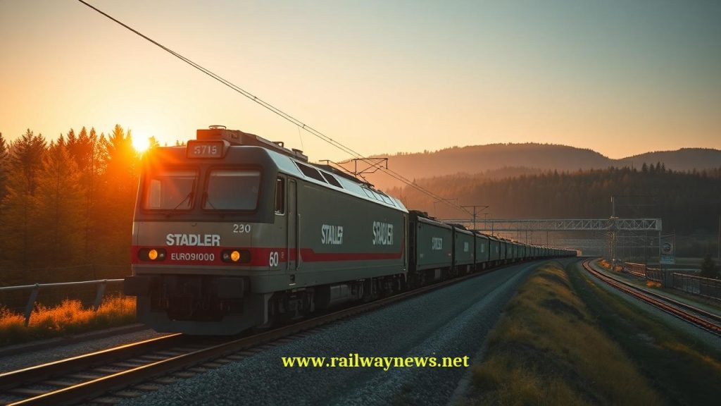
Phase Break Dynamics: Separating Power in Railway Electrification
What is a Phase Break in railways? Learn why electrification systems must separate AC phases to balance the national grid and prevent catastrophic short circuits.
⚡ In Brief
- A phase break separates two different AC phases on the same wire: Adjacent 25 kV feeding sections are supplied from different phases of the three-phase national grid — typically 120° apart in electrical angle. The instantaneous voltage difference between them can reach up to 43.3 kV (= √3 × 25 kV). Bridging that gap with a pantograph creates a phase-to-phase short circuit capable of producing fault currents exceeding 20 kA and destroying traction substation switchgear in milliseconds.
- The train must open its main circuit breaker before entering: A train approaching a phase break receives an instruction — via Eurobalise, lineside signal, or ETCS movement authority — to open its Vacuum Circuit Breaker (VCB) and coast. The pantograph remains raised and sliding, but the train’s electrical load is isolated from the contact wire before the first insulating element is reached. Failure to open the VCB before the phase break is a Category A failure mode in ETCS hazard logs.
- Length is a function of speed and train length: The neutral section (the dead zone of the phase break) must be long enough that no part of the train’s traction circuit bridges both live phases simultaneously. At 300 km/h, with a train 400 m long, a standard overlap phase break requires a neutral zone of at least 400 m plus safety margins — which is why HSR phase breaks occupy 400–600 m of track and are carefully located away from gradients where coasting stalls are possible.
- Germany’s 15 kV 16.7 Hz system faces a different problem: Unlike 25 kV 50 Hz systems fed from three-phase substations, the German and Swiss 15 kV 16.7 Hz single-phase railway supply is generated by a dedicated single-phase grid. Adjacent sections can be fed from the same phase — so German phase separations (Trennstellen) separate sections of the same phase for operational isolation, not phase-mismatch prevention. The voltage across such a separator is typically zero or very small, allowing trains to pass without opening the VCB.
- The 2009 ETR 500 Firenze incident set the modern benchmark for phase break failure analysis: An Italian high-speed ETR 500 trainset failed to open its VCB at a phase break on the Rome–Florence direttissima, bridging two 25 kV phases with its pantograph. The resulting arc event destroyed both pantographs, burned through 18 m of contact wire, and tripped the substation protection at both feeding ends. The root cause — a Eurobalise that had been physically displaced by track maintenance — drove a global revision of phase break detection redundancy requirements and the adoption of dual-balise group detection as the minimum standard for all ETCS Level 1 and 2 phase break approaches.
Shortly before 07:30 on 14 November 2009, an ETR 500 high-speed trainset operating service ES 9358 from Milan to Naples approached the phase break at kilometre post 247.4 on the Rome–Florence direttissima at approximately 270 km/h. The Eurobalise that should have triggered the train’s automatic VCB opening sequence 2,000 m before the phase separation had been physically displaced from its mounting position during a ballast tamping operation the previous night and was no longer transmitting. The train’s automatic systems detected no instruction to coast. The VCB remained closed. At 07:31:22, both of the train’s raised pantographs simultaneously contacted the contact wires of two 25 kV feeding sections supplied from phases separated by 120° of electrical angle — a condition that presented an instantaneous voltage difference of approximately 38 kV across the pantograph assembly. The resulting arc event ionised the air between the pantograph horns and the contact wire within 0.8 milliseconds, drawing a short-circuit current estimated at 18–22 kA. Both pantographs were destroyed. An 18-metre section of contact wire was burned through and fell across the track. The traction substations at Valdarno and Arezzo tripped simultaneously on overcurrent protection. Train ES 9358 decelerated to a standstill using emergency brakes, blocking the direttissima for 4 hours and 37 minutes during the morning peak. No passengers were injured — but the incident produced one of the most thorough failure analyses in European HSR history, and its findings directly shaped the current ETCS specification for phase break detection balise groups. Understanding why that Eurobalise mattered so much requires understanding the physics of phase breaks from first principles.
What Is a Phase Break?
A phase break — also called a neutral section, phase separation, or electrical neutral — is a point in a railway’s overhead contact system where the electrical supply changes from one AC phase to another, or where two independently fed sections are separated to prevent phase-to-phase fault current. The physical implementation creates a short segment of overhead wire that is either dead (neutral) or air-gapped, through which the train’s pantograph passes while the train’s main circuit breaker is open and no traction current is flowing.
The term “phase break” emphasises the electrical nature of the separation — two different phases of the grid. The term “neutral section” emphasises the physical implementation — a section of contact wire at zero potential, interposed between the two live sections. Both terms are correct and widely used; “neutral section” is the preferred term in Network Rail documentation and EN 50367, while “phase break” is more common in ETCS and traction power engineering contexts.
Why Phase Breaks Are Necessary: Three-Phase Grid Feeding of a Single-Phase Load
The national electricity grid is a three-phase system. The three phases — conventionally labelled L1, L2, and L3 — carry sinusoidal voltages at 50 Hz, each displaced 120° in time from the others. This arrangement is electrically balanced: the sum of the three phase voltages at any instant is zero, and the current drawn from each phase by balanced loads is equal, producing zero net current in the neutral conductor. The system is stable, efficient, and is what every power station, transmission line, and substation in Europe is designed to supply and receive.
A 25 kV AC railway is a fundamentally unbalanced single-phase load. A traction substation takes two of the three phases from the grid (for example, L1 and L2) and uses the voltage between them — which, for a 25 kV nominal system, is 25 kV — to feed the contact wire, with the rail providing the return. The next traction substation along the line takes the next phase pair (L2 and L3), and the one after takes L3 and L1. This rotation distributes the railway’s enormous single-phase load across all three grid phases over a route length, minimising the grid unbalance at any given point.
The Phase-to-Phase Voltage Problem
The consequence of this phase rotation is that two adjacent substations feed the contact wire with voltages that are not only different in phase angle but present a substantial voltage difference between them. The instantaneous voltage between two phases of a three-phase system at the same nominal voltage is given by:
Phase-to-phase voltage between adjacent 25 kV AC sections:
V_pp = √3 × V_phase = √3 × 25,000 V ≈ 43,301 V ≈ 43.3 kV
V_pp = √3 × V_phase = √3 × 25,000 V ≈ 43,301 V ≈ 43.3 kV
Peak instantaneous voltage (at worst-case phase angle coincidence):
V_peak = √2 × V_pp = √2 × 43,301 ≈ 61.2 kV
Short-circuit current if pantograph bridges both phases
(assuming system impedance Z_total ≈ 2 Ω at point of fault):
I_sc = V_pp / Z_total = 43,300 / 2 ≈ 21,650 A ≈ 21.6 kA
This exceeds the interrupting capacity of most rolling stock
vacuum circuit breakers (rated 25 kA) — but destroys pantographs
and contact wire within milliseconds before protection operates.
These numbers explain why bridging a phase break is catastrophic rather than merely disruptive. A 43.3 kV voltage presented across a pantograph assembly that spans perhaps 100–200 mm of air — on a contact wire nominally rated at 25 kV insulation — produces an immediate arc breakdown. The arc energy available from a 21 kA fault current at 43 kV is approximately 900 MW instantaneous power — an explosive event that vaporises copper contact wire and carbon pantograph strips within one electrical half-cycle (10 ms at 50 Hz).
Phase Break Physical Types: Insulators, Overlaps, and Air Gaps
Type 1 — Solid Section Insulator (SSI)
The solid section insulator is the simplest physical implementation. A length of electrically insulating material — typically a glass-reinforced polymer (GRP) or porcelain rod, 1.0–3.0 m long — is inserted into the contact wire, mechanically joining the two wire sections while electrically separating them. The insulator rod has the same cross-sectional profile as the contact wire (ribbed, to fit the same clamps and droppers) and a smooth underside for pantograph passage. The pantograph carbon strip slides over the insulating section without interruption.
The SSI is compact, inexpensive, and easy to install. Its limitations are significant for high-speed operation: the insulator material is harder and stiffer than copper contact wire, creating a mechanical impact as the pantograph transitions onto it. At speeds above approximately 160 km/h, this impact generates a measurable upward force spike that can exceed 300 N and cause momentary loss of contact. The insulating material also experiences electrical stress from the arcing that occurs when the VCB is opened slightly late — even a 0.1-second delay at 200 km/h means the pantograph is already 5.6 m into the insulated section. SSIs therefore predominate on conventional lines operating below 160 km/h and at station approaches, depot entrances, and maintenance overlap points where speed is limited.
Type 2 — Overlap Neutral Section (Air Gap Type)
The overlap neutral section creates a physical dead zone of overhead wire by running two separate contact wire sections in parallel — one from the upstream phase, one from the downstream phase — with their ends overlapping but not connected, separated laterally by the stagger differential. Between the two wire ends, a short section of neutral contact wire is suspended that is connected to neither live phase. The pantograph thus traverses a sequence: live wire A → neutral wire → live wire B, without any mechanical discontinuity in the sliding surface.
The neutral wire itself is typically 1–4 m long at conventional speeds and 30–100 m long on high-speed lines where the pantograph must complete its VCB opening and the transition fully before the next live section is touched. The live-wire overlap arms run parallel for a distance of 50–400 m on HSR, creating the “overlap zone” in which the phase transition architecture is visible from trackside as a distinctive double-wire arrangement above the track.
Type 3 — In-Flight Opening System (IFO) for Very High Speed
On lines operating above 250 km/h — France’s LGV network, the Shinkansen, HS2 — the overlap neutral section must be long enough that a full-length train (up to 400 m) can be entirely within the neutral section before the rear of the train exits the first live section. Simultaneously, the front of the train must not have reached the second live section. This requires a neutral zone of at minimum the full train length (400 m for a double TGV consist) plus stopping distance from the approach balise to the phase break entry (at 300 km/h and typical reaction times, a further 100–200 m). The total phase break infrastructure therefore occupies 400–600 m of contact wire, during which the train coasts on stored kinetic energy with no traction power available.
On steeply graded sections, this coasting requirement creates a timetable problem: a train decelerating through a 600 m neutral section on a 25‰ ascending grade may lose 15–25 km/h of speed, requiring subsequent re-acceleration and consuming additional energy. Phase break locations on HSR are therefore specified in the traction power design to avoid gradients steeper than 10‰ wherever possible, and on the LGV Méditerranée (opened 2001), three phase break locations required civil design modifications to reduce the local gradient specifically to allow TGV Duplex consists to transit at design speed without unacceptable speed loss.
What the Train Must Do: The Phase Break Passage Sequence
The safe passage of a train through a phase break requires a precisely sequenced set of actions, most of which are automated on modern rolling stock but which must be initiated by a reliable ground-to-train information trigger.
| Step | Action | Distance Before Phase Break Entry | Trigger |
|---|---|---|---|
| 1 | Train management system receives phase break advance warning | 2,000–4,000 m | Eurobalise group (ETCS) or advance signal marker |
| 2 | Traction power is reduced to zero; train enters coasting mode | 1,000–2,000 m | Automatic or driver-initiated on system command |
| 3 | Main VCB (Vacuum Circuit Breaker) opens — train electrically isolated | 200–500 m (before neutral entry) | Second Eurobalise group or signal (ETCS neutral section marker) |
| 4 | Pantograph remains raised; train coasts through neutral section | 0 — train traversing dead zone (30–600 m depending on system) | Mechanical — pantograph slides on neutral/dead wire |
| 5 | Train exits neutral section; downstream live wire contacted by pantograph | End of neutral zone | Third Eurobalise group (ETCS) or “end of neutral section” marker |
| 6 | VCB closes; traction power restored; normal operation resumes | 100–300 m after neutral exit | Automatic on VCB close command from balise or driver |
The ETCS specification (ERA/ESOS/010162 — ETCS System Requirements Specification, Subset-026) defines the neutral section as a specific ETCS object type within the movement authority. When a train operates under ETCS Level 1 or Level 2, the movement authority transmitted by trackside or RBC explicitly includes neutral section start and end positions with required VCB state (open/closed) for each. The train’s onboard computer enforces VCB opening at the correct position automatically, without driver action. The 2009 ETR 500 incident occurred under pre-ETCS conditions where VCB opening was triggered solely by the trackside balise, with no redundant system — a design inadequacy that ETCS Level 2 deployment has since eliminated on Italy’s alta velocità network.
Balise Groups and Phase Break Detection: The Post-2009 Standard
Prior to 2009, many 25 kV phase break approaches used a single Eurobalise to trigger VCB opening. The ETR 500 incident demonstrated the catastrophic consequence of single-balise failure — whether from displacement, contamination, or antenna fault — and drove a revision of ETCS SRS Subset-036 that mandated a minimum of two-balise groups for phase break approach on all ETCS-fitted lines.
The current standard requires:
- Balise Group A (Advance Warning): Located 2,000–4,000 m before the neutral section entry. Transmits the neutral section object to the onboard ETCS, placing the approaching section into the movement authority. This balise group can be a single balise; its failure is non-critical because Group B provides the VCB command.
- Balise Group B (VCB Opening Command): Located 200–500 m before the neutral section entry. Consists of a minimum of two balises (a linked pair) so that if one is lost, the second still transmits the VCB open command. Loss of both balises in Group B without the train having received the advance command from Group A triggers a supervised stop — the onboard ETCS applies service brake automatically, preventing the train from reaching the phase break without VCB opening.
- Balise Group C (VCB Close Command): Located 100–300 m after the neutral section exit. Transmits the VCB close command, restoring traction power. Also consists of two balises minimum.
On HS1 (the Channel Tunnel Rail Link), Network Rail’s implementation goes further: the phase break approach is monitored by a trackside transponder interrogator that actively confirms whether the approaching train’s VCB state (open or closed) has been reported via GSM-R or ETCS status message. If a train reports a closed VCB within 500 m of a phase break entry, an emergency signal aspect is generated on the preceding signal. This “confirmatory monitoring” approach — beyond the minimum ETCS SRS requirement — has been adopted as standard on Network Rail’s CP6 (2019–2024) phase break renewal programme.
The German Exception: 15 kV 16.7 Hz Single-Phase System
Germany, Austria, Switzerland, Norway, and Sweden operate their mainline railways on a 15 kV 16.7 Hz single-phase AC system — a historical legacy of the early 20th century when railway power was generated by dedicated single-phase generators running at one-third of grid frequency to reduce transformer iron losses. This system is fed from a dedicated single-phase railway electricity network (in Germany, the Bahnstrom-Netz operated by DB Energie GmbH at 110 kV, 16.7 Hz) that is separate from the national three-phase 50 Hz grid.
Because adjacent substations on the 15 kV 16.7 Hz system are fed from the same single-phase network — not from different phases of a three-phase grid — their supply voltages are nominally in phase with each other. The voltage difference across a section separator between two adjacent 15 kV sections is therefore close to zero under balanced conditions (it may reach a few hundred volts due to reactive voltage drops in the feeding network, but not the 43 kV of a 25 kV three-phase system). This means that 15 kV Trennstellen (section separators) are not phase breaks in the dangerous sense: the pantograph can bridge them without catastrophic fault current. Trains may pass a Trennstelle with the VCB closed, drawing current from one section while transitioning to the other, provided the section separator design allows it.
This fundamental difference has significant operational implications. German ICE trains do not have the phase break coasting requirement of French TGV or Italian ETR 500 trains. They can accelerate through a 15 kV section separator without power interruption. On mixed-system routes — such as the Paris–Frankfurt corridor where 25 kV 50 Hz in France transitions to 15 kV 16.7 Hz at the German border — multi-system trains (Thalys, ICE 3, Eurostar) carry both pantograph types, both VCB configurations, and must manage the transition at the border phase break as a 25 kV→15 kV system switch as well as a phase transition.
Phase Break vs. Section Insulator vs. Neutral Section: Full Comparison
| Parameter | Phase Break (25 kV 50 Hz) | Section Insulator (same phase) | 15 kV Trennstelle (16.7 Hz) |
|---|---|---|---|
| Electrical condition | Two different phases; up to 43.3 kV across gap | Same phase; ~0 V across insulator in normal service | Same phase (single-phase grid); typically <1 kV across |
| Bridging consequence | Phase-to-phase fault; arc explosion; 18–22 kA fault current | Harmless during normal ops; short-circuit if sections fed from different supplies during abnormal switching | Small circulating current; tolerable in most conditions |
| VCB requirement | Must be open before entry — mandatory | Not required under normal operation | Not required; train passes with VCB closed |
| Physical length | 1–3 m (SSI) to 400–600 m (HSR overlap) | 0.1–1.0 m (single insulator body) | 1–5 m (overlap insulator) |
| ETCS treatment | Dedicated neutral section object; dual balise groups mandatory | Not an ETCS object; no special train action required | No ETCS neutral section object; may be listed as info only |
| Grid load balancing role | Essential — prevents parallel feed from different grid phases | Operational isolation; no grid balancing function | Operational isolation; no phase balancing needed (single-phase grid) |
| Speed restriction | No speed limit, but coasting imposes kinetic energy loss | None | None |
| Timetable impact | Speed loss on grades; ~5–25 km/h depending on gradient and neutral length | None | None |
Phase Break Design Across Global HSR Systems
| System | Voltage / Freq. | Phase Break Type | Neutral Length | Detection Method | Max Speed |
|---|---|---|---|---|---|
| LGV (France, SNCF) | 25 kV 50 Hz | Air gap overlap | 500–600 m | Eurobalise (TVM 430 + ETCS) | 320 km/h |
| Alta Velocità (Italy, RFI) | 25 kV 50 Hz | Air gap overlap | 400–500 m | Dual Eurobalise groups (post-2009) | 300 km/h |
| HS1 (UK, Network Rail) | 25 kV 50 Hz | Air gap overlap | 400 m | ETCS L2 + confirmatory transponder | 300 km/h |
| Shinkansen (Japan, JR) | 25 kV 60 Hz / 25 kV 50 Hz | Air gap overlap | ~400 m (Tokaido) / ~350 m (Tohoku) | ATC transponders | 285–320 km/h |
| CRH (China, Beijing–Shanghai) | 25 kV 50 Hz | Air gap overlap | 400 m | CTCS-3 balise groups | 350 km/h |
| ICE (Germany, DB) | 15 kV 16.7 Hz | Overlap insulator (Trennstelle) | 5–20 m | LZB / ETCS (info only; no VCB command) | 300 km/h |
| Network Rail conventional (UK) | 25 kV 50 Hz | SSI (≤160 km/h) / overlap (HSR) | 1–3 m (SSI); 200–400 m (overlap) | TPWS + AWS marker; ETCS on upgraded routes | 200 km/h (conventional) |
| HS2 (UK, under construction) | 25 kV 50 Hz | Air gap overlap | 600 m (design, for 400 m trains) | ETCS L2; dual balise + transponder monitoring | 360 km/h (design) |
Autotransformer Systems and Phase Breaks: A Special Interaction
In an autotransformer (AT) 2×25 kV system, phase breaks have an additional electrical complexity that does not exist in simple 25 kV systems. The AT system supplies the contact wire at +25 kV and the negative feeder at −25 kV relative to the neutral rail, with autotransformers spaced every 10–15 km stepping the 50 kV feeder-to-feeder voltage down to 25 kV for the train. A phase break must interrupt not only the contact wire (+25 kV) but also the negative feeder (−25 kV) associated with the adjacent substation section — because if the negative feeders of two different-phase sections remain connected across the phase break, a feeder-to-feeder fault path exists at 86.6 kV (= √3 × 50 kV). AT system phase breaks therefore require simultaneous interruption of both the contact wire and the return feeder, producing a more complex four-conductor switching arrangement at each phase break location. This is why AT system phase breaks are designed and tested as complete substation-boundary switching assemblies, not as simple contact wire insulation segments.
Editor’s Analysis
The phase break is one of those engineering features that reveals, on examination, how deeply the constraints of the national electricity grid penetrate every operational detail of railway design. The location, length, and detection system of every phase break on a high-speed line is a direct consequence of decisions made in the grid design office — which phase pairs to use at which substations, how far apart to space them, how to balance the unbalanced single-phase load across the three-phase system. Railway traction engineers do not choose to have phase breaks; they inherit them from the structure of the power system they feed from. The history of phase break incidents — the ETR 500 in 2009, the Eurostar pantograph strikes on HS1 in the early 2010s, the recurring issues on the WCML in the UK during the 1990s — consistently shows the same failure pattern: a single detection system fails, and the layer of redundancy that should have caught the failure either does not exist or has degraded. The ETCS specification response has been textbook: mandate dual balise groups, add confirmatory monitoring, build VCB state into the movement authority so that passing a phase break with a closed VCB is treated as a safety-critical event, not merely an equipment malfunction. What remains less well addressed is the timetable impact of phase breaks on heavily graded HSR routes. A 600 m coasting zone on a 15‰ grade costs a high-speed train 20–30 km/h of speed and 90–120 kWh of energy per transit — multiplied across 200 daily paths, this is a measurable operational cost. The long-term solution is not better phase break design but elimination of phase breaks through the adoption of Scott transformers or other phase-balancing technology that allows adjacent sections to be fed from different phases without voltage differential at the boundary. Several Japanese Shinkansen sections now use this approach. If the economics of transformer cost versus operational efficiency are correctly assessed, this technology should be standard on all new HSR construction.
— Railway News Editorial
Frequently Asked Questions
1. What actually happens inside the train’s electrical system during a phase break — and why does lowering the pantograph fail as an alternative to opening the VCB?
When the VCB opens, it disconnects the train’s entire traction electrical circuit — inverters, traction motors, hotel power converter, and auxiliary systems — from the pantograph and contact wire. The pantograph remains raised and physically in contact with the overhead wire, but the circuit it feeds is open, so no current flows. The pantograph is simply a mechanical sliding contact; it has no electrical switching function of its own. As the pantograph travels through the neutral section dead wire, there is no current to interrupt and no arc. When it contacts the downstream live wire, it connects the VCB’s upstream terminal to the new phase voltage — but since the VCB is open, no current flows to the downstream (train) side of the circuit until the VCB is deliberately closed after exit. Lowering the pantograph would achieve the same electrical isolation, but it is mechanically incompatible with high-speed operation: a pantograph raised from lowered position at 300 km/h takes 8–15 seconds to reach full contact height and stabilise, during which the train is unpowered and the pantograph head is rising through a dynamic zone where contact wire height transitions and stagger changes create impact risks. More critically, pantograph lowering and raising operations generate large spark events as the carbon strip separates from the live contact wire — at 25 kV, the arc energy during pantograph drop can damage both the strip and the wire surface. The VCB is specifically designed to interrupt 25 kV load current without arcing damage (vacuum arc extinction in less than one half-cycle); it is the correct switching device. Lowering the pantograph is permitted only for emergencies and depot movements at very low speed.
2. How is a phase break located along a route — what determines where it goes, and what constraints prevent it from being placed wherever is most convenient?
Phase break location is determined by the interaction of three separate engineering disciplines: traction power design (substation feeding section boundaries), civil/track design (gradient profile), and operations planning (timetable critical section constraints). The traction power designer determines approximately where the feeding section boundaries must fall based on maximum substation spacing for voltage drop compliance — typically 20–40 km for 25 kV AT systems. This defines the kilometre-post range within which a phase break must be located. Within that range, the civil designer identifies sections with gradient less than 10‰ (preferably less than 5‰) where coasting losses are acceptable. The operations planner then checks that no phase break falls within a station approach or departure zone, a speed restriction zone, a curved section that complicates the overlap geometry, or within 3 km of another phase break (to prevent a train simultaneously traversing two neutral sections). On complex corridors — particularly approaches to major terminals where multiple HSR routes converge on constrained track — these constraints can become extremely difficult to satisfy simultaneously. The LGV Est Phase 2 (opened 2016) required a phase break to be located in a cut section with an upward gradient that, strictly, violated the design rule — the resolution was to extend the neutral section to 700 m (longer than any other on the LGV network) to ensure that even a delayed TGV Duplex consist decelerating on the grade would never stall with its pantograph bridging the live sections.
3. Can two trains be in the same neutral section simultaneously, and what happens to the second train’s traction during this overlap?
On conventional 25 kV systems with neutral sections of 30–200 m, simultaneous occupancy by two trains is geometrically impossible for any train longer than the neutral section, and unlikely for shorter trains given normal headway spacing. On HSR lines with 400–600 m neutral sections and headways of 3–5 minutes at 300 km/h, the average spacing between trains (25–40 km) makes simultaneous occupancy extremely rare but not physically prohibited. If two short trains (say, two Class 395 Javelin units at 113 m each) enter a 600 m neutral section with a 200 m separation, both can be simultaneously in the dead zone, both with open VCBs, both coasting. This presents no electrical hazard — both trains are isolated from each other and from the overhead wire. The operational risk is that the leading train, having exited and resumed traction, decelerates unexpectedly (emergency brake) while the following train is still in the neutral section with no traction available. ETCS movement authorities incorporate a buffer distance between trains that accounts for the additional coasting time in the neutral section when computing safe headways; the headway through a phase break zone is typically 30–60 seconds longer than headway on open track at the same speed. On the Shinkansen Tokaido, where peak headways of 3.5–4 minutes operate through the 350 m Odawara phase separation, the ATC system explicitly calculates extended buffer distances for trains in the neutral section approach zone.
4. What is a “scott transformer” connection, and how does it eliminate phase breaks entirely?
A Scott transformer connection is a three-phase to two-phase transformation scheme — invented by Charles F. Scott of Westinghouse in 1894 — that converts balanced three-phase power into two equal single-phase outputs at 90° phase difference (rather than the 120° difference between standard three-phase windings). By feeding two adjacent traction substation sections from these two 90°-displaced outputs rather than from two of the three 120°-displaced grid phases, the voltage difference across the section boundary is reduced from √3 × V_phase (43.3 kV for 25 kV) to the algebraic sum of two 25 kV voltages displaced by 90°, which equals √2 × 25 kV = 35.4 kV. While this is still a significant voltage, more sophisticated Scott arrangements combined with phase-compensating capacitors can reduce the boundary voltage to below 5 kV — low enough that an overlap section insulator, rather than a full neutral section, is sufficient for safety. More advanced implementations, including the “modified Scott” and “V-connection” transformer arrangements used on several JR East Shinkansen substations since 2004, reduce the section boundary voltage to near-zero by precisely matching the magnitudes and phases of the two outputs. These arrangements allow trains to pass section boundaries with VCBs closed and at full traction — eliminating the neutral section entirely. The cost is a more complex and expensive substation transformer arrangement and precise reactive power compensation. The economic justification is strong on high-frequency, high-speed services where each timetable path through a conventional neutral section costs 15–30 seconds of runtime: across 200 daily paths at €50 per train-minute of delay savings, the substation premium pays back in under 10 years on a busy HSR line.
5. What happens when a train stalls in a neutral section — and how is it recovered?
A train stalling in a neutral section — with its pantograph on the dead overhead wire, VCB open, and insufficient kinetic energy to exit under momentum — is one of the most operationally disruptive incidents on an electrified HSR line. It blocks both the track section it occupies and the OCS sections on either side (since neither can be re-energised while the train’s pantograph spans the neutral zone boundary). Recovery options are limited and all involve significant delay. The preferred procedure on most networks is: (1) confirm the VCB is open and the pantograph is not bridging both live sections; (2) lower the pantograph; (3) if traction cannot be restored from on-board auxiliary power or battery, contact the network control centre to arrange a rescue locomotive or a permitted electric push from the following train (if it can reach the stalled train from the live section). On 25 kV lines with short neutral sections (30–100 m), a stalled train can often be pushed through by a following train making physical buffers contact — both trains’ pantographs are then on opposite live sections and neither bridges the neutral section. On HSR with 400–600 m neutral sections, physical push contact is impossible as the pushing train cannot reach the stalled train without its own pantograph entering the dead zone. In these cases, the stalled train must be evacuated (on long neutral sections in tunnels, this can be a safety-critical event) and towed clear by a diesel or battery-electric rescue locomotive introduced from the nearest access point. The 2018 stalling incident on the LGV Est — a TGV Duplex that stalled in the Nanteuil neutral section on a 12‰ upgrade during extreme cold (−18 °C battery capacity loss) — required 2 hours 40 minutes to clear, disrupting 34 trains and costing SNCF an estimated €1.2 million in delay penalties. The incident accelerated adoption of enhanced traction battery capacity requirements for all new HSR rolling stock procured under French rail infrastructure standards.

Railway infrastructure, rolling stock and transport technologies specialist focused on global rail industry developments, high-speed rail systems, signaling technologies and freight transportation. Covering railway investments, public transport modernization, rail operations and international mobility projects across Europe, Asia and North America.
RELATED POSTS

June 4, 2026 11:05 am
California High-Speed Rail Authority awarded a $3.5 billion track and...

June 4, 2026 6:22 pm
Network Rail and HS2 demolishes two strategic rail bridges, Saltley...

June 1, 2026 9:19 pm
300 IBEW signal workers initiated a strike against Canadian Pacific...

June 2, 2026 8:44 am
⚡ In Brief: The UK Office of Rail and Road...
June 2, 2026 10:31 am
⚡ In Brief: The UK’s Office of Rail and Road...
June 2, 2026 11:37 am
⚡ In Brief: The UK’s Office of Rail and Road...