
Bridging the Gap: The Critical Role of Railway Gangways
How do passengers walk safely between speeding train cars? Discover the engineering behind the Gangway—the flexible bridge ensuring connectivity and protection.
⚡ In Brief
- A gangway must accommodate up to six simultaneous degrees of relative motion between adjacent cars: As a train negotiates a horizontal curve, the two adjacent carbodies yaw relative to each other (rotation in the horizontal plane). On a vertical curve or hump, they pitch relative to each other (rotation in the vertical plane). On a section of track with differential super-elevation, they roll relative to each other. On jointed track, they translate vertically relative to each other (bounce). They also translate laterally (sway) and longitudinally (buff and draft forces). A high-speed gangway bellows must seal against weathering, aerodynamic pressure, and fire propagation while absorbing all six of these relative motions simultaneously, at amplitudes that at minimum maintenance curve radii can reach ±5° yaw, ±3° pitch, ±2° roll, ±30 mm vertical translation, ±50 mm lateral translation, and ±80 mm longitudinal compression/extension — without tearing, buckling, or losing its environmental seal.
- The aerodynamic pressure seal is the most demanding requirement for high-speed gangways: When a 300 km/h train enters a single-track tunnel, the air pressure differential between the interior and exterior of the train rises by approximately 3–5 kPa within 1–2 seconds — equivalent to ascending 300–500 m in altitude. If this pressure differential is transmitted to the passenger saloon through unsealed gangways, passengers experience painful ear pressure changes (barotitis). The Shinkansen Tōkaidō tunnel design specification of the 1960s, which first quantified this requirement, drove the development of hermetically sealed gangway bellows capable of maintaining an interior-exterior pressure differential of 4 kPa while accommodating the full range of relative car motions at operating speed. This specification, refined over decades, is the basis of today’s EN 14752 tunnel pressure standard requirements for HSR gangways.
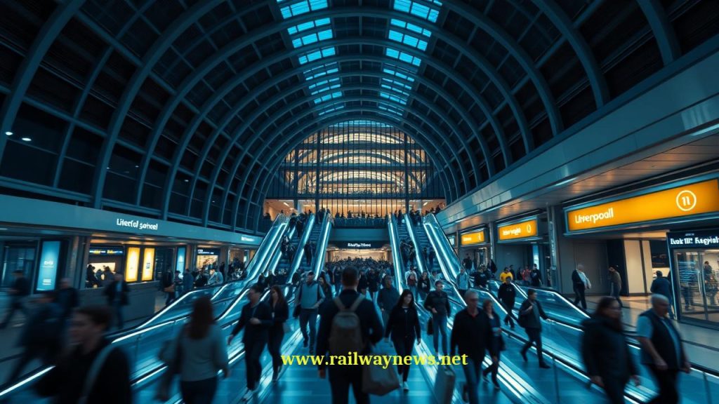
- Wide open gangways on metro stock increase usable passenger capacity by 3–10% for the same vehicle length: On a conventional metro train with vestibule-type gangways (a narrow passage with doors at each end), passengers cannot stand in the inter-car connection zone during peak crowding because the constricted passage space is uncomfortable and doorways block flow. On a wide open gangway train — where the full carbody width extends continuously through the inter-car connection — the connection zone becomes productive standing space equivalent to approximately 3–4 m² of additional floor area per connection. For an 8-car train with 7 inter-car connections, this represents 21–28 m² of additional usable floor area — equivalent to approximately 40–60 additional standing passengers at 4 persons/m² — without any increase in train length.
- EN 45545-2 governs gangway material fire performance and defines the hazard level that dictates which materials are permissible: The gangway bellows, being located at the inter-car boundary where fire spread is most dangerous, is classified under EN 45545-2 (Railway applications — Fire protection — Part 2: Requirements for fire behaviour of materials and components) at Hazard Level HL3 — the most stringent classification — for all materials within the gangway structure. HL3 requires: flame spread rate of zero (material must self-extinguish); heat release rate below 90 kW/m²; smoke optical density below a specified threshold; and no dripping of flaming material. These requirements effectively mandate halogen-free, intumescent-coated, or inherently fire-retardant elastomers and thermoplastics for all gangway bellows materials, and exclude conventional chloroprene rubber (Neoprene) from use in HL3 gangway applications unless specially treated.
- Evacuation through gangways is the primary emergency egress route when door access is impossible: In the event of a train fire between stations, train-to-train collision, or infrastructure obstruction preventing door opening, passengers must be able to evacuate through the inter-car gangways to reach an adjacent car whose doors can be opened. TSI Safety in Railway Tunnels (SRT) requires that gangways on trains operating in tunnels longer than 1 km must provide a clear evacuation width of at least 700 mm and must remain passable (not blocked by fire, smoke, or structural deformation) for a minimum of 15 minutes after the initiating event. Gangway design for evacuation compliance requires self-closing fire doors, smoke-sealed bellows, and structural integrity under the deformation loads imposed by a post-collision or post-derailment train geometry.
At 01:25 on 6 July 1978, a Motorail sleeping car train operated by British Rail on service 1M70 from Penzance to Glasgow was approaching Taunton in Somerset when a fire was discovered in sleeping car SC2 — a vehicle at the rear of the formation. The fire had started from an overheated electric heating element in a passenger berth. By the time it was discovered, it had spread to the synthetic foam mattress and the compartment’s curtains. A conductor attempting to contain the fire opened the end door of SC2 to retrieve equipment from the adjacent car SC3. The open gangway door — the hinged fire door that separated the two vehicles at their inter-car connection — allowed the fire to propagate into SC3 within approximately 60–90 seconds. By the time the train stopped on the Taunton avoiding line and the fire brigade arrived, three sleeping cars were involved. Twelve passengers died, trapped in their berths. The Department of Transport investigation (published as the Coleman Report, 1978) identified the open gangway door — which had been secured in the open position by a passenger earlier in the journey using a latching hook designed for daytime operational convenience — as the primary mechanism of fire propagation from SC2 to SC3. A self-closing fire door, held open by the latching hook against its design intent, had become the path of a fatal fire. The Coleman Report’s primary structural recommendation was that inter-car gangway fire doors on passenger trains must be provided with self-closing mechanisms capable of overcoming any force a passenger could apply to hold them open, and that latch mechanisms allowing fire doors to be held open must be removed or replaced with fail-safe designs that release under abnormal temperature conditions. These recommendations were implemented in British Rail rolling stock over the following decade and, in evolved form, are now embedded in EN 45545-2’s requirements for inter-car fire separation — requirements that govern the gangway fire doors on every new train placed in service across the European Union. Twelve lives were the cost of learning that the convenience of an open gangway door and the safety function of a closed fire door cannot coexist in the same mechanism.
What Is a Railway Gangway?
A railway gangway — also called an inter-car gangway, vestibule connection, diaphragm, or end connection — is the structural and environmental interface between two adjacent railway vehicles. It comprises: the bellows (a flexible membrane spanning the gap between the vehicle end faces, sealing against weather, noise, and aerodynamic pressure while accommodating relative motion); the floor plate (bridging the gap at floor level, typically a hinged or sliding plate covering the gap between car floors); and where fitted, the gangway door or fire door (a self-closing panel providing thermal and smoke separation between vehicles in fire conditions).
The gangway’s functions span five disciplines simultaneously: structural (transmitting longitudinal buff and draft forces at the vehicle connection); dynamic (accommodating all relative motions between adjacent carbodies without tearing or loss of seal); environmental (excluding weather, wind noise, and tunnel pressure fluctuations from the passenger saloon); fire safety (containing fire and smoke to the initiating vehicle for a defined period); and accessibility (providing a continuous, step-free path for passenger and crew movement between vehicles). The governing European standards are EN 16286-1 (Railway applications — Gangway systems — Part 1: Main requirements for gangways between vehicles used for passenger transport) for design and performance, EN 45545-2 for fire material requirements, and EN 14752 (Railway applications — Side entry systems) for the sealing performance in tunnel pressure scenarios.
Six Degrees of Relative Motion: The Gangway’s Geometric Challenge
The fundamental engineering challenge of gangway design is geometric: the flexible bellows must seal a gap between two rigid carbodies that are simultaneously moving relative to each other in up to six independent ways. Understanding each degree of motion and its maximum amplitude at the design minimum curve radius defines the bellows’ required flexibility envelope — the spatial volume that the bellows must fill without tearing or applying excessive restoring forces to the carbody end frames.
Relative motion amplitudes at minimum track geometry (R = 150 m):
1. YAW (horizontal rotation about vertical axis):
θ_yaw = L_car / R = 20 m / 150 m = 0.133 rad = 7.6°
→ Bellows must accommodate ±7.6° horizontal deflection
2. PITCH (rotation about lateral horizontal axis — vertical curves):
Typical vertical curve radius R_v = 500 m minimum:
θ_pitch = L_car / R_v = 20 / 500 = 0.040 rad = 2.3°
→ Plus track twist component: up to ±3° total
3. ROLL (rotation about longitudinal axis — cant differential):
Maximum cant differential between adjacent bogies on transition:
θ_roll ≈ ±2.5° (EN 13848 track twist limit)
4. LATERAL TRANSLATION (carbody sway):
Secondary suspension lateral travel ±50 mm per carbody
Combined: up to ±80 mm relative translation
5. VERTICAL TRANSLATION (bounce):
Secondary suspension vertical travel ±30 mm per carbody
Combined: up to ±40 mm relative vertical translation
6. LONGITUDINAL TRANSLATION (buff/draft):
Coupler compression stroke: up to −80 mm (buff)
Coupler extension: up to +30 mm (draft)
→ Bellows must compress and extend by these amounts
All six degrees simultaneous at R = 150 m (depot/shunting scenario):
Bellows volume swept = complex 3D envelope
Bellows material must accommodate all combinations without
exceeding its elongation limit (typically 300–500% for EPDM)
The Bellows Material: EPDM vs Neoprene vs Polyurethane
The bellows is manufactured from an elastomeric fabric — a woven textile reinforcement (typically polyester or aramid fibre) bonded to a rubber or thermoplastic elastomer face. Three material families dominate current production. EPDM (ethylene propylene diene monomer rubber) provides excellent weathering and ozone resistance, moderate fire performance (passes HL2 without treatment; requires halogen-free additive packages for HL3), and good flexibility across a wide temperature range (−40°C to +125°C). It is the dominant material for mainline passenger and suburban rolling stock gangway bellows in Europe. Neoprene (chloroprene rubber) was the historical standard due to its inherent flame retardancy from its chlorine content; post-EN 45545-2 adoption it has become problematic for HL3 applications because combustion of chlorine-containing materials produces toxic hydrogen chloride gas — a smoke toxicity failure mode addressed in EN 45545-2’s CT (combustion toxicity) requirements. Halogen-free polyurethane thermoplastic elastomers, introduced in the 2010s, offer superior HL3 performance with zero halogen combustion products, but require careful formulation to maintain the low-temperature flexibility required for cold-climate operation without bellows stiffening that would impose excessive forces on the carbody end frames.
Aerodynamic Sealing: Tunnel Pressure and High-Speed Gangways
When a high-speed train enters a tunnel, the air in the tunnel cannot escape fast enough around the train, creating a compression wave ahead of the train and a low-pressure region behind. The pressure differential between the compressed air ahead and the undisturbed atmospheric pressure outside the tunnel section produces a rapid pressure rise at the train surface — and through any unseal in the train envelope, inside the passenger saloon.
Tunnel Entry Pressure Calculation
Maximum pressure change rate for passenger comfort (EN 14752):
Comfort limit: ΔP ≤ 1,000 Pa per second (mild discomfort threshold)
Comfort limit: ΔP ≤ 3,000 Pa over any 10-second period
Pressure rise at tunnel entry (simplified blocked ratio model):
ΔP ≈ ½ × ρ × v² × (1 − β²) / β²
where:
ρ = air density = 1.225 kg/m³
v = train speed (m/s)
β = blockage ratio = train cross-section / tunnel cross-section
ICE 3 in German NBS single-track tunnel (β = 11.7/63 = 0.186):
v = 83.3 m/s (300 km/h)
ΔP = ½ × 1.225 × 83.3² × (1 − 0.186²) / 0.186²
= ½ × 1.225 × 6,939 × 0.965 / 0.0346
= ≈ 11,900 Pa = 11.9 kPa total wave amplitude
Rate at tunnel entry (pressure rise over ~1 second entry transient):
dP/dt ≈ 11,900 / 1.0 = 11,900 Pa/s
→ Far exceeds 1,000 Pa/s passenger comfort limit if transmitted to saloon
→ Gangway seal must limit interior dP/dt to ≤ 1,000 Pa/s
Allowable gangway leakage rate for a 10-car ICE 3 (saloon volume ~1,000 m³):
For interior pressure to change at ≤ 1,000 Pa/s:
Max leakage flow = 1,000 Pa/s × 1,000 m³ / (γ × P_atm)
≈ 1,000 × 1,000 / (1.4 × 101,325) ≈ 7.0 m³/s total
This 7.0 m³/s total leakage budget must be shared across:
9 inter-car gangways + 2 end faces + all door seals + window seals
→ Gangway leakage allowance: approximately 0.5–0.8 m³/s per gangway
The 0.5–0.8 m³/s leakage allowance per gangway at an 11.9 kPa differential represents a very tight sealing requirement — equivalent to an effective leakage gap of approximately 2–4 cm² total across the entire gangway bellows perimeter. Achieving this requires inflatable seals (additional pneumatic bellows pressed against the carbody end face by compressed air when the gangway bellows is deployed) rather than relying on the static contact pressure of the bellows alone. ICE 3 gangway connections include an inflatable lip seal around the full perimeter of the bellows-to-carbody contact that is pressurised to approximately 0.3 bar above ambient when the gangway is deployed in service, ensuring that the contact pressure is maintained regardless of bellows fatigue or aging. The Shinkansen equivalent — in tunnels with even higher blockage ratios (some Shinkansen tunnels have β = 0.25–0.30) — uses double-layer inflatable seals with active pressure monitoring and automatic pressure adjustment if seal pressure falls below specification during tunnel transit.
Wide Open Gangways: Capacity Engineering for Urban Transit
The wide open gangway — a full-width inter-car connection without separating doors, creating a continuous open tube along the train’s full length — has become the standard for new metro, light rail, and commuter rail rolling stock procured since approximately 2000. Its adoption is driven by a quantifiable capacity benefit that becomes particularly important at peak crowding levels.
Capacity Quantification
On a conventional compartmented train with vestibule gangways, the inter-car connection zone — typically 0.6–0.8 m wide and 0.8–1.2 m long, with doors at each end — is not usable standing area during peak crowding. Passengers avoid standing in the constricted passage because the doors impede flow, the passage width is uncomfortable for multiple simultaneous users, and the lack of handholds makes it difficult to maintain balance. On a wide open gangway train, the connection zone has the same internal width as the vehicle saloon — typically 2.2–2.6 m — and is equipped with handholds and floor markings identical to the main saloon. It is fully productive standing area.
| Parameter | Conventional Vestibule Gangway | Wide Open Gangway |
|---|---|---|
| Internal width at connection | 0.6–0.8 m (passage between door frames) | 2.2–2.6 m (full carbody width) |
| Connection zone length | 0.8–1.2 m | 0.6–1.0 m (bellows width only) |
| Usable floor area at connection | ~0.5 m² (passage only, not useful) | ~2.0–2.6 m² per connection (fully usable) |
| Additional passengers per connection at 4/m² | 0 | 8–10 per connection |
| 8-car train (7 connections) extra capacity | 0 | 56–70 additional passengers |
| Passenger flow throughput (persons/min) | 12–18 (single file through passage) | 45–60 (multi-file through full width) |
| Boarding/alighting dwell time impact | Baseline | 5–15% reduction (better load distribution) |
| Revenue surveillance / CCTV coverage | Blind spots at vestibule junction | Line-of-sight through full train length |
The London Underground S Stock Case
Transport for London’s S Stock fleet — introduced from 2009 on the Circle, District, Hammersmith & City, and Metropolitan lines — was the first major London Underground fleet to feature full-width walk-through gangways on all vehicles. The TfL specification for the S Stock required that the inter-car connections accommodate a minimum clear width of 1,800 mm (versus the previous C and D Stock’s 650 mm vestibule passage) to enable the declared capacity increase. Bombardier’s design provides a 1,900 mm clear gangway width at all connections, with a floor plate covering the car junction gap and handrails continuous through the gangway zone. TfL’s post-introduction analysis of passenger distribution on peak-period trains found that the walk-through gangway had shifted approximately 8% of the standing passenger load from the door areas (where conventional trains concentrate passengers due to difficulty moving to the car centre) toward the car centres and gangway zones — effectively distributing the load more evenly and reducing the boarding/alighting friction at door areas. This 8% improvement in load distribution translated to a measured reduction in average dwell time at busy stations of approximately 3.2 seconds per stop — a commercially significant improvement on a metro system where schedule recovery time is scarce.
Fire Containment: EN 45545-2 and Gangway Door Requirements
The gangway occupies the most fire-critical position in the vehicle’s structural layout — it is the only structural path through which fire can spread from one vehicle to another without involving the track or the external environment. Fire separation between vehicles is therefore a design priority addressed by EN 45545-2, the TSI SRT (Safety in Railway Tunnels), and national regulations in every major railway jurisdiction.
EN 45545-2 Material Requirements for Gangways
EN 45545-2 classifies railway components by Hazard Level (HL1 through HL3) based on the consequence of fire at that location. Inter-car gangways, being at the vehicle boundary where fire spread to adjacent vehicles occurs, are classified at HL3 — the highest hazard level — in all operating conditions and for all train categories. HL3 material requirements specify:
- Flame spread (EN ISO 11925-2 test): Flame travel must not exceed 150 mm on the sample surface within 60 seconds of ignition — effectively self-extinguishing behaviour.
- Heat release (EN 45545-2 requirement R1): Maximum heat release rate (MARHE) ≤ 90 kW/m² measured in the cone calorimeter test at 50 kW/m² irradiance.
- Smoke production (EN ISO 5659-2 test): Optical density Ds ≤ 300 at 4 minutes at 25 kW/m² irradiance.
- Combustion toxicity (EN 45545-2 requirement R7): Concentration indexes for CO, HCN, HCl, HBr, HF, SO₂, and NO₂ must not exceed specified limits — this is the requirement that eliminates conventional chloroprene rubber (Neoprene) from HL3 applications, as its combustion produces HCl above the allowed threshold.
Self-Closing Fire Doors: The Taunton Lesson Applied
EN 45545-3 (Design measures — Appendix requirements for fire protection) and the TSI SRT require that fire doors in inter-car gangways on trains operating in tunnels be self-closing — that is, they must return to the closed position under their own spring or weight mechanism when released, and must not incorporate a latching mechanism that allows them to be held open against the closing force. The maximum allowable closing force (the force a user must apply to hold the door open) is defined as a human comfort maximum of 60 N — high enough that the door closes reliably but low enough that a passenger can push through in an emergency. This requirement directly embeds the Taunton 1978 lesson: the latching hook that held the fire door open, eliminating the closing force, must not exist in any design. Some operators’ specifications go further: the Thameslink Programme specification for the Class 700 fleet (adopted 2016) requires fire door closers to be thermally activated, so that if a fire door is deliberately held open by a passenger and a fire occurs, the thermal actuator releases any mechanical restraint and allows the spring closer to operate regardless of applied human force. This is the fail-safe application of the Taunton lesson at a mechanical design level.
Evacuation Geometry: TSI SRT Requirements
The TSI Safety in Railway Tunnels (Commission Regulation (EU) No 1303/2014) specifies that trains operating through tunnels exceeding 1,000 m must provide inter-car gangways that remain passable for passenger evacuation for at least 15 minutes following the initiating event (fire or collision). The evacuation geometry requirements are:
TSI SRT gangway evacuation minimum dimensions:
Clear width (at narrowest point, including any floor plate): ≥ 700 mm
Clear height (above floor, no obstruction): ≥ 1,800 mm
Floor plate load capacity (to carry evacuating passengers): ≥ 3 kN/m² (300 kg/m²)
Passability after post-collision deformation: Gangway must remain
navigable after vehicle end deformation of up to 100 mm longitudinal shortening
Maintained evacuation path after fire initiation: 15 minutes minimum
→ Bellows must not collapse into gangway space (blocking passage)
→ Fire door must remain operable (not seized by heat distortion)
→ Floor plate must not deform to create trip hazard
Maximum passenger evacuation flow rate required:
Train capacity / 15 minutes = e.g. 600 pax / 15 min = 40 persons/min
At 700 mm clear width: approximately 40–50 persons/min achievable ✓
Smoke sealing performance (TSI SRT Annex C):
Gangway bellows must maintain interior smoke concentration below:
CO: 5,000 ppm (non-incapacitating for 15 min evacuation)
→ Requires sealed bellows perimeter with maintained seal pressure
Gangway Design Families: From Bellows to Integral Connections
| Design Type | Construction | Pressure Sealing | Curve Capability | Primary Application |
|---|---|---|---|---|
| Canvas diaphragm (legacy) | Pleated canvas bellows with steel end frames; rubber lip seal | Low — weather seal only; no pressure sealing | ±5–8° yaw; ±3° pitch | Heritage and older mainline stock; freight locomotive cab gangways |
| Rubber bellows (sealed) | EPDM or polyurethane fabric bellows with inflatable lip seal; floor plate | High — 4 kPa differential at design leakage rate | ±7° yaw; ±3° pitch; ±2° roll | Mainline and HSR passenger stock (ICE, TGV, Pendolino, Class 800) |
| Wide open gangway (metro) | Full-width bellows; hinged or sliding floor bridge; no separating doors | Medium — weather seal; not rated for high tunnel differential | ±8–12° yaw (larger for tight depot radii) | Metro, light rail, urban commuter (S Stock, Aventra, Inspiro) |
| Integral articulated connection (Jacobs bogie) | Bellows over Jacobs bogie; floor bridge spans bogie; no floor gap | Medium–high (bellows sealed; floor continuous) | Limited by Jacobs bogie yaw (±5°) | TGV, Eurostar, Thalys, low-floor tram articulated joints |
| Tightlock gangway (North American passenger) | Rigid diaphragm panel with rubber perimeter seal; no bellows pleats | Low–medium (weather seal) | ±6° yaw (limited by rigid panel geometry) | Amtrak Superliner/Viewliner, VIA Rail, Canadian passenger rail |
Gangway Systems in Service: Key Examples
| Vehicle | Gangway Type | Key Specification | Notable Feature |
|---|---|---|---|
| ICE 3 (Class 406 / 407, DB) | Sealed rubber bellows with inflatable lip seal | 4 kPa pressure sealing; EPDM bellows; HL3 fire rating | Bellows reinflated automatically if lip seal pressure drops below threshold during tunnel transit; monitored by traction management system |
| TGV Duplex (SNCF) | Integral Jacobs bellows (over Jacobs bogie); sealed | Continuous floor at 580 mm over Jacobs bogie; sealed for LGV tunnel pressure | Double-deck gangway connects both floors; lower deck floor plate is structural (carries passenger load over bogie gap) |
| London Underground S Stock (Bombardier) | Wide open walk-through gangway | 1,900 mm clear width; no doors; continuous handrails; HL3 bellows material | Fire door requirement waived under LU special conditions agreement — LU tunnels are shorter than TSI SRT 1,000 m threshold for most sections; smoke control relies on ventilation system |
| Thameslink Class 700 (Siemens Desiro City) | Wide open gangway with thermally-activated fire door | 1,800 mm clear width; thermally-activated closer at all connections; HL3 materials throughout | Post-Taunton lesson applied: thermal actuator releases any mechanical restraint if fire temperature detected; fire door closes automatically regardless of passenger intervention |
| N700S Shinkansen (JR Central) | Fully sealed bellows with active pressure management | Double-layer inflatable seal; automatic pressure compensation; 6 kPa rating | Tokaido tunnels have β = 0.22–0.28; highest tunnel pressure environment of any regular passenger service; active seal management prevents ear-popping at 285 km/h |
| Bombardier Aventra (Class 387 / 710 / 720) | Wide open walk-through gangway | 2,100 mm clear width; sliding floor plate; fire door at specific designated positions per TSI SRT compliance | Fire doors at every 4th vehicle end (not every gangway) — TSI SRT compliance achieved through fire door spacing rather than universal door fitting, reducing passenger flow restriction |
Editor’s Analysis
The gangway is the component that most clearly illustrates the tension between the competing demands placed on railway vehicles by accessibility, capacity, aerodynamic performance, and fire safety — because it is the component where all four requirements converge in the same 0.8 square metres of structure. A wide open gangway maximises capacity and accessibility and is the right answer for metro and commuter rail. A hermetically sealed bellows with inflatable lip seal maximises aerodynamic performance and is the right answer for high-speed rail in tunnels. A fire door at the inter-car boundary maximises fire safety and is the right answer for long-tunnel compliance. These three correct answers are partially incompatible: a wide open gangway without doors fails the TSI SRT fire safety test in tunnels longer than 1 km; a hermetically sealed high-speed bellows severely restricts the width available for walk-through capacity; a fire door at every connection reduces passenger flow throughput by 25–35% compared to an open gangway. The engineering response to this incompatibility — typified by the Bombardier Aventra’s spacing of fire doors at every fourth connection rather than every connection — is pragmatic and largely correct: it achieves TSI compliance without completely sacrificing the flow benefits of the wide open design. But it is worth noting that the Taunton 1978 fire, which killed twelve people through an open fire door held by a passenger, is now precisely the failure mode that a thermally-activated fire door closure (as specified for the Class 700) is designed to prevent — a failure mode that an every-fourth-car fire door strategy cannot address in the three carbodies between those fire doors. The engineering argument for fire doors at every inter-car boundary is not merely regulatory conservatism; it is a documented causal pathway to passenger fatalities. The capacity argument for fewer fire doors is economically and operationally real. The resolution of that tension is a policy decision as much as an engineering decision, and the railway industry’s answer to it varies by jurisdiction in ways that reflect different implicit valuations of these competing goods rather than clear evidence about which approach is actually safer over the full range of fire scenarios.
— Railway News Editorial
Frequently Asked Questions
1. Why do some high-speed trains have windows in the gangway area through which you can see the track below — is this a safety concern?
On some older high-speed trainsets — notably early TGV and Eurostar Class 373 formations — the floor plate covering the Jacobs bogie junction has a small transparent or mesh panel through which the bogie and track are visible beneath. This is intentional and serves two engineering purposes. First, it allows depot staff to visually inspect the Jacobs bogie condition from inside the train without requiring a pit or external access — a practical maintenance benefit in a formation where bogie access from below requires synchronised jacking. Second, on the TGV Duplex, the lower deck floor at the inter-car connection is structurally supported by the Jacobs bogie frame rather than by a cantilever from the adjacent carbodies, and the structural design of the floor plate requires a slightly open construction around the bogie pivot bearing housing to accommodate the differential motion between the floor and the bogie frame during vehicle dynamics. The visible gap is the consequence of this structural accommodation. Safety concern is minimal because the gap is covered by a close-clearance metal grating whose mesh size (typically 20×20 mm) is too small for any foot or object to penetrate, and the grating is rated to carry the full floor load capacity (5 kN/m² per EN 13749 floor requirement). On newer designs (TGV Avelia Horizon / TGV M), the floor plate is fully solid, using a revised structural arrangement that eliminates the visible gap while maintaining the Jacobs pivot accommodation — largely for passenger perception reasons, as the gap was a frequent source of passenger complaints despite presenting no actual hazard.
2. How does a gangway on a tilting train handle the fact that the two adjacent carbodies can be tilted at different angles simultaneously?
This is one of the most geometrically complex requirements imposed on a tilting train gangway, and it is handled through a combination of bellows flexibility and tilt synchronisation engineering. On a tilting train like the Pendolino (Class 390), adjacent carbodies are controlled by separate tilt actuators — each actuator receives a tilt command from the control system based on its own bogie’s curve sensing. As a train traverses the transition spiral at a curve entry, the leading carbody begins tilting before the trailing carbody — the leading bogie is in the curve before the trailing bogie reaches it. During this transition period, two adjacent carbodies can be at different tilt angles simultaneously — the difference being the tilt angle corresponding to the carbody-to-carbody distance divided by the transition curve length. For a Pendolino with 26 m carbodies and a 300 m transition spiral, the maximum simultaneous tilt difference between adjacent cars is approximately 26/300 × 8° = **0.69°** — small enough that the bellows can accommodate it as a combination of roll and pitch at its normal operating deflection. For this reason, tilting train gangway specifications include a “differential tilt” requirement that the bellows must accommodate — typically ±1° additional roll beyond the non-tilting design roll limit — ensuring that the bellows does not become the limiting factor in how fast the tilt command can be applied to successive cars. The floor plate at the tilting inter-car connection requires special attention: a rigid floor plate bridging two cars at different tilt angles would be in twist, creating a tripping hazard. Modern tilting train gangway floor plates use a centre-hinged design where each half of the floor plate is connected to its adjacent carbody and the two halves are free to rotate relative to each other about the centre hinge, allowing each half to follow its carbody’s tilt angle independently.
3. What is the aerodynamic drag contribution of inter-car gangways — and does gangway design affect train energy consumption?
Inter-car gaps are a significant aerodynamic drag source on high-speed trains, and gangway design that minimises the gap and its exposure to the external airstream meaningfully reduces energy consumption. The aerodynamic drag of an inter-car gap depends on three factors: the gap width (the longitudinal distance between adjacent car end faces at the gangway position), the gap depth (how far the recessed area extends below the train profile), and the smoothness of the bellows surface relative to the surrounding car body. Experimental data from wind tunnel tests and full-scale aerodynamic measurements (notably the DB Aerodynamics Research Programme of the 1990s, conducted on ICE 1 and ICE 2 formations) showed that each inter-car gap contributes approximately 2–4% of the total aerodynamic drag of the formation, depending on gap geometry. For a 300 km/h, 400-tonne train consuming 8 MW of traction power, 3% of aerodynamic drag per inter-car gap equates to approximately 240 kW per gap, or approximately 2.16 MWh per 300 km route — at 0.10 €/kWh, approximately €216 per train journey per gap. For a 9-gap ICE 3 formation, the total inter-car gap aerodynamic cost is approximately €1,944 per 300 km journey. Reducing gap width from 80 mm to 40 mm reduces this cost by approximately 30% — €580 per journey. This quantification explains why ICE 3 and subsequent HSR designs invest significantly in tight gap control (bellows pre-tensioned to maintain small gap width under draft loading), smooth bellows surface profiles (minimising the step between car body and bellows surface), and aerodynamically profiled gap fillers (shaped covers that partially fill the inter-car recess). The Shinkansen design standard for inter-car gap aerodynamic drag is the most stringent globally — the N700S inter-car gap geometry was validated in JR Central’s Maglev wind tunnel (which has sufficient blockage ratio for realistic Shinkansen aerodynamic simulation) and reduced inter-car aerodynamic drag by 7% compared to the N700 predecessor through gap reduction and bellows surface contouring.
4. Can a gangway bellows be replaced in service without removing the vehicle from the formation — or does bellows replacement always require depot access?
On a conventional independently-bogied multiple unit where the adjacent carbodies are connected by a simple coupler and the gangway bellows is bolted to the car end frames, bellows replacement can in principle be performed at a siding or platform: the coupler is disconnected, the bellows is unbolted from both car end frames, the new bellows is offered up and bolted in, and the coupler is reconnected. In practice, this is physically demanding work in a confined space and is typically performed at depot with proper access equipment — but it does not require any lifting or separation of the carbodies beyond the coupler disconnect. The time is approximately 4–8 hours per bellows. On an articulated Jacobs-bogie formation (TGV, Eurostar), the situation is more complex. The Jacobs bogie supports both adjacent car ends and cannot be withdrawn without lifting both carbodies. The gangway bellows on a Jacobs connection is bolted to both car end frames and surrounds the Jacobs bogie pivot housing. Replacement requires either: lifting both carbodies simultaneously on synchronised jacks to access the bellows attachment bolts around the bogie pivot (which is inside the bellows envelope); or disconnecting one carbody from the Jacobs bogie and temporarily supporting it on stands, then removing the bellows from the disconnected side, replacing it, reconnecting it to the repaired side, and then reconnecting the carbody. Either approach is a significant planned maintenance task requiring 1–3 days of depot time. This maintenance penalty is a known trade-off of the Jacobs bogie architecture — the gangway bellows is one of several components whose replacement is more complex than on a conventional formation, and its service interval (typically 1–2 million km for the bellows fabric) is a factor in the total life cycle cost calculation for Jacobs-bogie fleet operation.
5. What happens to the gangway in a crash — does it stay intact, and can passengers use it for evacuation after a collision?
Gangway behaviour in crash scenarios is governed by the same structural hierarchy that governs the rest of the vehicle end structure: the crash management zone is designed to absorb energy by controlled deformation while preserving the survival space and the evacuation path. For the gangway specifically, EN 16286-1 requires that the gangway connection remain passable (≥ 700 mm × 1,800 mm clear opening) after the EN 15227 C-I design collision scenario (36 km/h closing speed between two identical formations). This requirement constrains the crash management zone design: the deformable underframe elements that absorb crash energy must not fold into the gangway connection zone, and the bellows attachment frames must not buckle in a way that collapses the bellows into the passage area. In well-designed EN 15227-compliant formations, post-collision gangway passability is typically confirmed by finite element simulation of the full crash event and verified in physical crash testing. The TSI SRT adds the further requirement that the gangway remain passable for 15 minutes after a tunnel fire event — meaning the bellows must not collapse through thermal degradation (which is why HL3 material requirements apply even to the bellows body, not just the fire door). In the real-world TGV Atlantique collision at Lézignan-la-Cèbe (2000, described in the Jacobs Bogie article), post-incident inspection of the surviving intact gangways on the rear cars confirmed that all gangway connections remained physically passable — the evacuation path through the formation was intact from car 3 to car 10 even after the severe impact at car 1. This confirmed both the crashworthiness of the Jacobs articulated structure and the integrity of the gangway as an evacuation route in a real, high-energy impact event.

Railway infrastructure, rolling stock and transport technologies specialist focused on global rail industry developments, high-speed rail systems, signaling technologies and freight transportation. Covering railway investments, public transport modernization, rail operations and international mobility projects across Europe, Asia and North America.
RELATED POSTS

June 4, 2026 11:05 am
California High-Speed Rail Authority awarded a $3.5 billion track and...

June 4, 2026 6:22 pm
Network Rail and HS2 demolishes two strategic rail bridges, Saltley...

June 1, 2026 9:19 pm
300 IBEW signal workers initiated a strike against Canadian Pacific...

June 2, 2026 8:44 am
⚡ In Brief: The UK Office of Rail and Road...
June 2, 2026 10:31 am
⚡ In Brief: The UK’s Office of Rail and Road...
June 2, 2026 11:37 am
⚡ In Brief: The UK’s Office of Rail and Road...