
UIC 897-20: Welder Qualification Framework Needs Shop Floor
UIC 897‑20 Chapter 8 provides a robust framework for initial qualification, but it does not—and cannot—guarantee consistent weld quality on the shop floor.
⚡ IN BRIEF
- The 1999 Shinkansen Wake‑Up Call: In December 1999, JR East discovered fatigue cracks in the aluminium carbodies of its E4 series Shinkansen trains, traced to improper welding parameters and inadequate welder qualification. This incident triggered a global tightening of standards, directly influencing the development of UIC 897‑20 Chapter 8 for fusion welding of aluminium alloys.
- ISO 9606‑2 as the Technical Backbone: UIC 897‑20 Chapter 8 aligns with ISO 9606‑2, the international standard for qualification testing of welders for aluminium and its alloys. It defines essential variables like parent material groups, welding processes (GTAW/GMAW), thickness ranges, and joint configurations, ensuring consistent skill assessment across Europe and beyond.
- Stringent Acceptance Criteria: The leaflet mandates both non‑destructive (visual, penetrant, radiographic) and destructive (transverse tensile, root and face bend) tests on test pieces. For a typical 10 mm thick 6082‑T6 alloy, a transverse tensile strength of at least 215 MPa (minimum of base metal) and 180° bend without cracks are required.
- Essential Variables & Re‑Qualification: Any change in welding process, filler metal classification (e.g., ER4043 vs. ER5356), or parent material thickness beyond the certified range (e.g., from 6–12 mm to >12 mm) voids the approval. Re‑qualification is mandatory every two years, with a continuous skill maintenance log, as per ISO 9606‑2.
- Safety and Documentation: The leaflet integrates with EN 15085, the European standard for welding of railway vehicles. It requires a documented Welding Procedure Specification (WPS) and a Welder Performance Qualification (WPQ) record, which must be kept for at least 15 years to ensure traceability throughout the vehicle’s lifecycle.
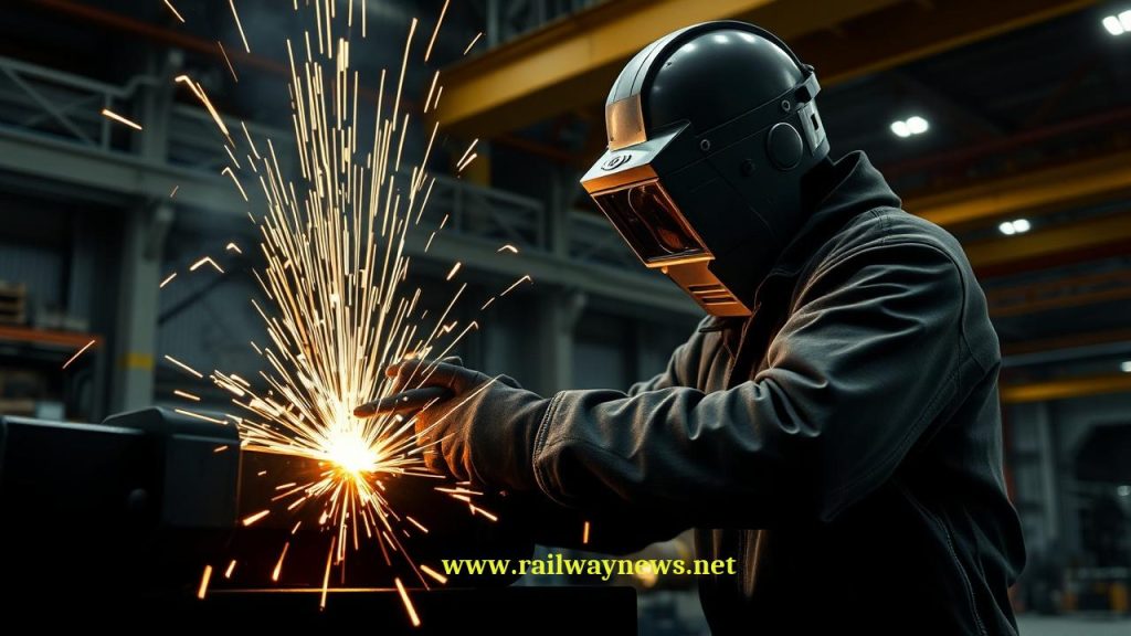
On a cold December morning in 1999, a routine ultrasonic inspection at JR East’s Sendai depot revealed a 45‑mm fatigue crack in the underframe of an E4 series Shinkansen—a train less than three years old. The crack, originating from a fusion weld in the aluminium alloy car body, had propagated through 70% of the base metal thickness, jeopardizing the structural integrity of the entire carbody. Subsequent fleet‑wide inspections found similar defects in 18 out of 208 cars, all traced back to inadequate welder qualification and poor heat input control during manufacturing. The incident sent shockwaves through the global railway industry, forcing a paradigm shift: aluminium welding could no longer rely on generic training; it demanded a rigorous, standardized approval system. UIC Leaflet No: 897‑20 – Chapter 8 emerged as the definitive response, harmonizing the technical specification for welder approval across Europe and beyond, ensuring that every fusion weld on an aluminium railway vehicle is executed by a demonstrably competent professional.
What Is UIC Leaflet 897‑20 Chapter 8 & Why It Matters
UIC Leaflet 897‑20 – Chapter 8 is the International Union of Railways’ technical specification that defines the mandatory requirements for the approval of welders performing fusion welding on aluminium and aluminium alloys used in railway rolling stock and infrastructure. It is built on the framework of ISO 9606‑2 (Qualification testing of welders – Fusion welding – Part 2: Aluminium and aluminium alloys) and is further tailored to the specific safety and durability demands of rail applications. The leaflet establishes a structured qualification process that includes theoretical knowledge exams, practical welding tests, and continuous skill assessment. It covers all fusion welding processes common in rail manufacturing, significantly Gas Tungsten Arc Welding (GTAW/TIG) and Gas Metal Arc Welding (GMAW/MIG), and addresses critical parameters such as heat input, interpass temperature, and shielding gas composition. By mandating a uniform, documented approval system, it eliminates the variability of national standards and ensures that any welded joint—whether on a high‑speed train’s roof extrusion or a tram’s bolster—meets the highest structural integrity requirements.
1. The Core Technical Framework: ISO 9606‑2 & Essential Variables
At the heart of UIC 897‑20 lies a matrix of essential variables that define the scope of a welder’s approval. Any change outside these variables requires re‑qualification. Key essential variables include:
- Parent Material Group: Aluminium alloys are classified into groups (e.g., Group AL 1 for non‑heat‑treatable 5xxx series, Group AL 2 for heat‑treatable 6xxx/7xxx series). A welder approved for AL 2 cannot weld AL 1 without re‑test.
- Welding Process: Separate approvals for GTAW (manual TIG) and GMAW (semi‑automatic MIG). Hybrid processes like laser‑hybrid require additional testing.
- Thickness Range: The approval covers a thickness range of 0.5× to 2× the test piece thickness. For a test on 10 mm plate, the certified range is 5–20 mm.
- Welding Positions: Tests are performed in specific positions (PA, PC, PF, etc.). A welder qualified in the flat position (PA) is not authorized for overhead (PE).
These variables are meticulously recorded in the Welder Performance Qualification (WPQ) record, which becomes a legal document accompanying the vehicle throughout its service life.
2. Qualification Testing: From Test Pieces to Destructive Examination
The qualification procedure under Chapter 8 consists of three phases: theoretical assessment, practical test welding, and inspection/evaluation. The practical test requires the welder to produce a test piece (e.g., a butt weld on 10‑mm‑thick 6082‑T6 plate) using the intended welding process and position.
The test piece undergoes:
- Visual Examination (VT): No cracks, incomplete fusion, or excessive reinforcement (≤ 2 mm for thickness ≥ 10 mm).
- Non‑Destructive Testing (NDT): Typically liquid penetrant testing (PT) for surface defects; for safety‑critical components, radiographic testing (RT) or ultrasonic testing (UT) is required to detect internal porosity and lack of fusion.
- Destructive Testing:
- Transverse tensile test: Two specimens must achieve a tensile strength ≥ 90% of the minimum specified for the base metal (e.g., ≥ 215 MPa for 6082‑T6).
- Root and face bend tests: Four specimens are bent 180° over a former of diameter 4× specimen thickness; no cracks exceeding 3 mm are permitted.
- Macro‑examination: At least one cross‑section is examined for complete penetration, fusion, and absence of significant porosity (e.g., cumulative pore area < 2% in the weld cross‑section).
Only when all these tests pass does the welder receive the official approval, valid for two years.
3. Material-Specific Challenges: Aluminium Alloys in Railway Construction
Aluminium’s high strength‑to‑weight ratio makes it ideal for rail vehicles, but its weldability is highly sensitive to alloy composition and heat treatment. The leaflet provides guidance on the most common alloys used in rail:
| Alloy Series | Typical Application | Weldability & Key Risks |
|---|---|---|
| 6005A, 6082 (Al‑Mg‑Si) | Extruded profiles for car bodies, underframes | Good weldability; risk of reduced strength in HAZ (softening). Use ER4043 or ER5356 filler; post‑weld heat treatment often required. |
| 5083, 5754 (Al‑Mg) | Non‑structural panels, fuel tanks | Excellent weldability, good corrosion resistance. Typically used in as‑welded condition. |
| 7020, 7N01 (Al‑Zn‑Mg) | High‑strength structural components (e.g., Shinkansen bolsters) | High strength, but highly sensitive to hot cracking and hydrogen porosity. Requires careful heat input control (< 1.5 kJ/mm) and filler alloy matching (e.g., ER5356). |
The standard emphasizes that welders must understand the specific alloy’s behavior, including the need for preheating (typically 100–150°C for 7xxx series) and interpass temperature limits to avoid liquation cracking.
4. Welding Procedure Specification (WPS) & Quality Management Integration
UIC 897‑20 does not stand alone; it integrates with EN 15085‑2 (Welding of railway vehicles – Part 2: Requirements for welding manufacturers). The WPS is the critical link. For each approved welder, a WPS must define:
- Welding parameters: current (A), voltage (V), travel speed (mm/s), heat input (kJ/mm). A typical GMAW heat input calculation: H = (U × I × 60) / (1000 × v), where U = voltage, I = current, v = travel speed (mm/min). For 6082‑T6, H should be kept between 0.8 and 1.2 kJ/mm to maintain mechanical properties.
- Shielding gas: Typically pure argon (99.99%) for GTAW; Ar‑He mixtures for GMAW to improve penetration.
- Filler metal: Classification according to ISO 18273. For 6xxx series, ER4043 (AlSi5) is common; for 5xxx and 7xxx, ER5356 (AlMg5) is preferred.
- Preheat and interpass temperatures: Measured using contact thermocouples or infrared thermometers.
The combination of a validated WPS and a qualified welder (as per Chapter 8) forms the basis for “Production Welding” under EN 15085, ensuring that every weld meets the required Quality Level (CL) – CL 1 for safety‑critical components (e.g., bogie frames), CL 2 for secondary structures.
GTAW vs. GMAW for Aluminium Railway Welding
Both processes are permitted under UIC 897‑20, but they differ significantly in application, skill requirements, and weld characteristics. The table below compares key aspects:
| Parameter | GTAW (TIG) | GMAW (MIG) |
|---|---|---|
| Heat Input Control | Excellent; pulsed current allows precise control, reducing HAZ softening. | Moderate; high deposition rates can lead to higher heat input if not optimized. |
| Weld Quality (Porosity) | Low porosity with proper technique and shielding; susceptible to tungsten inclusions. | Higher risk of hydrogen porosity; requires strict cleanliness and gas shielding. |
| Deposition Rate | Low (0.5–2 kg/h); ideal for thin sections, root passes, and precision work. | High (3–10 kg/h); suitable for thick sections and long seams. |
| Operator Skill Level | High; requires manual dexterity and fine control. | Medium; can be semi‑automatic, but still requires skill for parameter setup. |
| Typical Rail Applications | Root passes on bogie frames, repair welding, thin‑walled extrusions. | Longitudinal seams on car bodies, thick‑section butt welds. |
| Approval Validity (ISO 9606‑2) | Separate qualification for GTAW; cannot be cross‑used for GMAW. | Separate qualification for GMAW; pulsed GMAW considered a separate process. |
Editor’s Analysis: The Gap Between Qualification and Reality
UIC 897‑20 Chapter 8 provides a robust framework for initial qualification, but it does not—and cannot—guarantee consistent weld quality on the shop floor. The two‑year requalification cycle mandated by ISO 9606‑2 is often treated as a bureaucratic checkpoint rather than a true skill assessment. Many manufacturers rely on a single test piece per welder, which may not capture the variability of real production conditions, such as access restrictions, tack welding sequences, or the inevitable variations in joint fit‑up. Moreover, the standard’s focus on destructive testing of mock‑ups fails to address the most critical issue: the welder’s ability to maintain parameters in the presence of magnetic arc blow, poor shielding gas coverage, or contaminated base material—all common in railway manufacturing.
What is urgently needed is a shift toward continuous monitoring and digital traceability. Some forward‑looking rolling stock manufacturers now integrate welding data loggers that record actual current, voltage, and travel speed for every weld, cross‑referencing them with the welder’s approved WPQ. This creates a “digital twin” of the welder’s performance, allowing early detection of drift. The next revision of UIC 897 should incorporate such online monitoring as a mandatory element for quality level CL1 welds. Until then, the standard remains a necessary but incomplete safeguard.
— Railway News Editorial
Frequently Asked Questions (FAQ)
1. Why does aluminium welding require a separate qualification from steel welding?
Aluminium and steel have fundamentally different thermal, electrical, and metallurgical properties. Aluminium has a thermal conductivity approximately five times higher than steel, which means heat dissipates rapidly, requiring higher amperages and precise preheating to avoid lack of fusion. Its oxide layer (Al₂O₃) melts at over 2000°C, far above the base metal’s melting point (around 660°C), demanding aggressive oxide removal and often AC GTAW for cleaning. Moreover, aluminium is highly susceptible to hydrogen porosity and solidification cracking, especially in heat‑treatable alloys. A welder trained on steel will instinctively use techniques (e.g., weaving, high travel speed) that are detrimental to aluminium. Therefore, ISO 9606‑2 (and by extension UIC 897‑20) mandates a separate, dedicated approval to ensure the welder understands and can manage these unique challenges.
2. What is the difference between a Welding Procedure Specification (WPS) and a Welder Performance Qualification (WPQ)?
A WPS is a documented set of welding parameters (current, voltage, travel speed, filler metal, etc.) that has been tested and validated to produce a sound weld on a specific material and joint configuration. It is a recipe. A WPQ, on the other hand, is the record that a specific welder has demonstrated the skill to follow that WPS and produce acceptable welds. Under EN 15085 and UIC 897‑20, you cannot have one without the other: a WPS without a qualified welder is theoretical; a welder without a WPS has no defined process to follow. Both documents must be available at the workplace and are audited by certification bodies (e.g., DB Systemtechnik, Lloyd’s Register) during manufacturing approvals.
3. How is heat input controlled in aluminium welding, and why is it critical?
Heat input (kJ/mm) is the energy transferred to the weld per unit length. For aluminium, excessive heat input causes two main problems: (1) softening of the heat‑affected zone (HAZ) in heat‑treatable alloys like 6082, potentially reducing strength by 30–40%; (2) increased distortion and residual stresses. The standard formula H = (U × I × 60) / (1000 × v) is used to calculate it. For 6xxx series alloys, the target heat input is typically between 0.8 and 1.2 kJ/mm. To achieve this, welders often use pulsed GMAW or GTAW, where the background current maintains the arc while peak current melts the filler. Modern welding machines display real‑time heat input, allowing the welder to adjust travel speed or current to stay within the WPS limits.
4. What non‑destructive testing methods are required for aluminium welds under UIC 897‑20?
While the leaflet does not prescribe a specific NDT method for every weld, it references EN 15085 and ISO 17635, which define acceptance levels. For aluminium, the most common NDT methods are: Visual Testing (VT) – mandatory for all welds, checking for cracks, incomplete fusion, and undercut; Liquid Penetrant Testing (PT) – standard for surface‑breaking defects, essential on root passes and final finishes; Radiographic Testing (RT) – required for quality level CL1 welds to detect internal porosity and lack of fusion, with acceptance criteria per ISO 10675‑2; Ultrasonic Testing (UT) – increasingly used for thicker sections (>10 mm) to detect planar defects like lack of sidewall fusion. The choice depends on the component’s criticality, material thickness, and accessibility.
5. How often must a welder be re‑qualified, and what happens if they fail?
ISO 9606‑2 (and UIC 897‑20) mandates re‑qualification every two years to maintain approval. However, if a welder has not performed any welding of the relevant process and material within the last six months prior to the expiry date, they must undergo a new practical test. If a welder fails the re‑qualification test, their approval is immediately suspended. The manufacturer must then either retrain the welder and issue a new test piece (after a cooling‑off period typically set by the certification body) or remove them from production welding. Continuous monitoring is also required: if a welder produces three consecutive weld repairs on the same component due to their own defects, the WPQ is considered invalid until re‑testing.

Railway infrastructure, rolling stock and transport technologies specialist focused on global rail industry developments, high-speed rail systems, signaling technologies and freight transportation. Covering railway investments, public transport modernization, rail operations and international mobility projects across Europe, Asia and North America.
RELATED POSTS
June 8, 2026 5:59 am
EN 50129 explained: safety-related electronic systems for railway signalling —...