
The Umbrella System: What is Automatic Train Control (ATC)?
ATC is the overarching class of signaling systems that integrates safety, operation, and supervision. It is often described by the formula: ATC = ATP + ATO + ATS, providing a complete solution for regulating train movements.
⚡ In Brief
- Automatic Train Control (ATC) is the umbrella term for the complete integrated system of train safety, operation, and supervision — comprising ATP (Automatic Train Protection), ATO (Automatic Train Operation), and ATS (Automatic Train Supervision) — that together manage every aspect of how trains move safely and efficiently on a railway.
- The three ATC components have clearly separated roles: ATP enforces safety (a train cannot exceed safe limits regardless of driver action); ATO drives the train (executes the optimised speed profile between stations); ATS manages the network (monitors, regulates, and recovers the service against the timetable). Each can fail independently without compromising the others’ core function.
- ATC with continuous cab signalling — where speed authorisation is transmitted to the train in real time rather than displayed on lineside signals — enables both higher operational speeds and denser headways than traditional fixed-block signalling, because the driver always knows exactly what speed is permitted at their current position rather than at the next signal location.
- ETCS (European Train Control System) is the European implementation of ATC: ETCS provides the ATP layer, ATO over ETCS provides the driving layer, and ERTMS Traffic Management provides the supervision layer — all integrated into a single standardised architecture designed to replace over 20 incompatible national systems.
- The degree of ATC integration determines the Grade of Automation (GoA): GoA1 (ATP only, manual driving), GoA2 (ATP + ATO, driver present), GoA3 (ATP + ATO + ATS, train attendant), GoA4 (full ATC, no staff on board). Every GoA4 metro in the world operates on complete ATC integration.
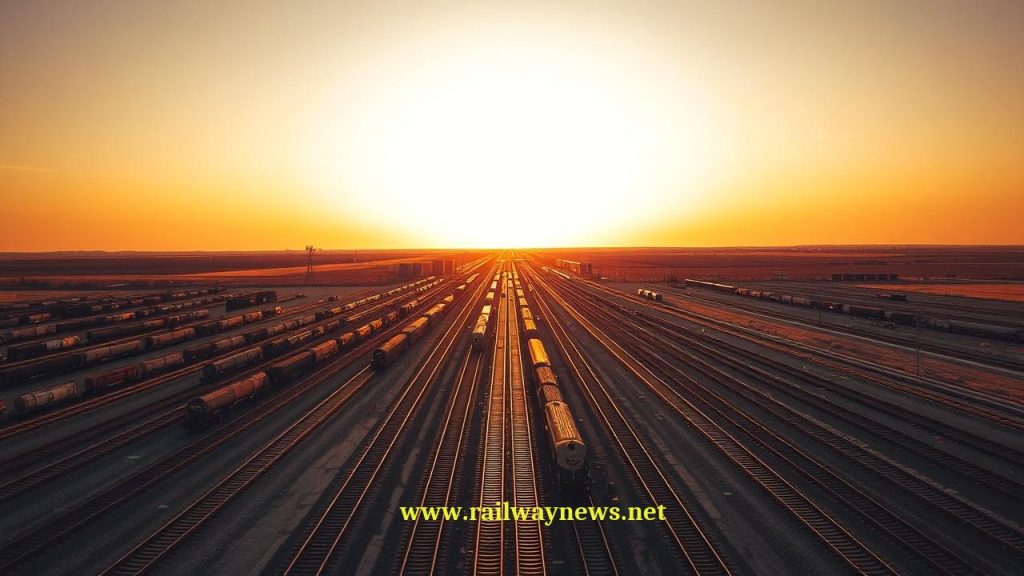
At 06:47 on a Tuesday morning in Singapore, a train on the North-South Line departs Woodlands station. No driver is at the controls. The platform screen doors have confirmed all passengers are aboard. The train’s ATO system has received its departure authority. The EVC has cleared the route. The Train Management System has pre-set the timetable departure. The CBTC system confirms a clear section ahead. The train accelerates smoothly, following a pre-calculated speed profile that will deliver it to the next station on time, at the exact platform stopping mark, consuming the minimum energy consistent with the schedule. The entire sequence — from departure trigger to platform stop — involves zero human decision-making.
This is ATC in its fullest expression: not a single system but a layered architecture of three interdependent control functions, each essential, each operating in its own domain, each providing information to and receiving constraints from the others. Understanding ATC means understanding not just what each component does, but why the three-layer architecture exists — and what is lost when any layer is absent.
What Is ATC?
Automatic Train Control is the integrated system architecture that collectively manages the safe and efficient movement of trains. In most engineering contexts, ATC is defined by the formula:
ATC = ATP + ATO + ATS
Each component is distinct in its function, its safety integrity level, its failure modes, and its interface with the driver and the network. None is sufficient alone:
- ATP without ATO: The train is protected but not automatically driven — a human driver operates within the safety envelope. This is GoA1/GoA2 operation: useful for mainlines, insufficient for driverless metro.
- ATO without ATP: The train is automatically driven but with no safety enforcement — a software bug, an incorrect timetable instruction, or a hardware fault in the ATO system could command the train into a dangerous situation with no independent check. This configuration is not used in railway practice because ATO is explicitly a non-safety-critical system.
- ATS without ATO/ATP: Network traffic is managed but individual trains are not controlled — essentially a computerised operations centre managing a manually driven railway.
The Three Layers: Functions, Roles, and Interfaces
| Layer | Full Name | Primary Function | Safety Level | Can Override | Analogy |
|---|---|---|---|---|---|
| ATP | Automatic Train Protection | Enforces safe limits; applies brakes if speed or authority violated; cannot be overridden in normal service | SIL 4 — safety-critical | Overrides both ATO and driver commands when safety is at risk | The safety supervisor — always has the last word |
| ATO | Automatic Train Operation | Drives the train: controls throttle, coasting, braking, and precision station stopping based on schedule and ATP authorities | Non-safety-critical (operational) | Overrides manual driving in automated modes; overridden by ATP | The driver — operates within safe limits set above |
| ATS | Automatic Train Supervision | Manages network: timetable adherence, route setting, conflict resolution, service regulation and recovery | Non-safety-critical (operational) | Sets route requests (via interlocking) and departure authorities (to ATO); cannot override ATP | The operations manager — plans and adjusts the service |
How the Three Layers Interact
The three ATC layers interact through defined interfaces that enforce a strict authority hierarchy:
ATS → ATO: ATS provides ATO with the departure authority (the time the train should depart and its destination) and any regulation instructions (hold for late connections, skip a station, run express to recover time). ATO uses this information to calculate the departure timing and the speed profile for the journey. ATS cannot command ATO to perform an action that would require violating ATP limits.
ATO → Train systems: ATO outputs traction and braking commands to the train’s propulsion and braking systems, executes precision station stopping, and manages door interlock sequences (authorising door opening when the train is correctly stopped at the platform). In GoA2, ATO requires a human driver to initiate the departure; in GoA3/4, ATO initiates departure autonomously when the departure authority is received.
ATP → Everything: ATP is the highest-authority layer. When ATP determines that the train’s speed or position exceeds the permitted envelope — based on the movement authority from the interlocking (via RBC in ETCS L2, or balise in L1) — it commands immediate brake application regardless of what ATO or the driver is commanding. ATP’s brake command cannot be countermanded by ATO or the driver in normal service. The only way to override ATP is by isolating it, which requires controller authority and imposes a severe speed restriction.
ATC and the Interlocking: The Missing Fourth Component
The ATP + ATO + ATS formula omits a fourth, essential component that makes ATC work: the interlocking. The interlocking is the safety-certified system that actually moves points, locks routes, and verifies track sections are clear before issuing movement authorities. It is not usually included in the “ATC = ATP + ATO + ATS” formula because it is considered infrastructure rather than train control — it is a fixed installation, not a component of the onboard or operations systems.
But the functional relationship is clear: the interlocking is what generates the movement authorities that ATP enforces, the routes that ATS requests, and the safety envelope within which ATO operates. Without a functioning interlocking, no component of ATC has the information it needs to function correctly. The complete system is more accurately described as:
Complete train control: Interlocking + ATP + ATO + ATS
(Interlocking = infrastructure; ATP + ATO + ATS = train control system)
Cab Signalling: ATC’s Most Visible Characteristic
The feature that most clearly distinguishes ATC-equipped railways from conventionally signalled ones is cab signalling — the provision of speed and authority information directly to the driver’s display in the cab, rather than (or in addition to) lineside signals. Traditional railways communicate with drivers through a series of coloured lights visible at intervals alongside or above the track. A driver sees a yellow signal and knows they must be prepared to stop at the next signal — but they do not know from this signal how fast they are going, whether they are within a correct braking profile, or what the track ahead looks like beyond the next signal.
Cab signalling changes this fundamentally:
- The driver receives a continuous, real-time update of the maximum permitted speed at their current position — not at the next signal location.
- The ATP system continuously supervises compliance with that limit and acts immediately if it is exceeded, without waiting for the driver to reach a signal displaying a restrictive aspect.
- The Planning Area (in ETCS) or equivalent display shows upcoming restrictions several kilometres ahead, allowing the driver (or ATO) to plan the optimal braking profile rather than reacting to signals.
Cab signalling enables both safety and operational improvements: it allows lineside signals to be removed entirely (reducing infrastructure maintenance cost and removing signal sighting limitations), and it allows tighter headways because the authority boundary is defined by train position rather than fixed signal locations.
ETCS: The European ATC Architecture
ETCS (European Train Control System) is Europe’s implementation of ATC, designed to replace over 20 incompatible national systems. The ETCS architecture maps directly onto the ATC formula:
| ATC Layer | ETCS Component | Key Standards |
|---|---|---|
| ATP | ETCS OBU / EVC (Onboard); RBC + Eurobalise (Trackside) | ERA/ERTMS/015560; IEC 62280; EN 50128/50129 |
| ATO | ATO over ETCS (ATO-OB); ERA/ETCS ATO specification | ERA ATO Functional Requirements; UNISIG Subset for ATO |
| ATS | Traffic Management System (TMS); ARS (Automatic Route Setting) | EN 50128; national operational specifications |
ATC vs CBTC: Complementary, Not Competing
CBTC (Communications-Based Train Control) is often discussed alongside ETCS, and the relationship between them causes confusion. CBTC is not an alternative to ATC — it is an implementation of ATC, specifically optimised for urban metro and light rail applications:
| Parameter | ETCS | CBTC |
|---|---|---|
| ATC formula | ATP + (ATO over ETCS) + TMS = complete ATC | ATP (CBTC core) + ATO + ATS = complete ATC |
| Primary application | Mainline, high-speed, intercity | Metro, urban rail, light rail |
| Positioning | Eurobalise spot fix + radio odometry | Continuous radio positioning (WiFi or dedicated) |
| Block type | Fixed block (L1/L2) or moving block (L3) | Moving block (standard) |
| Standardisation | Fully standardised — interoperable across Europe | IEEE 1474 framework; vendor-specific implementations |
| GoA capability | GoA1–GoA2 operational; GoA3/4 with ATO over ETCS | GoA2–GoA4 (most modern deployments are GoA4) |
ATC and Grade of Automation: The Complete Picture
The relationship between ATC components and Grades of Automation clarifies exactly which components are required at each GoA level:
| GoA | ATP Required | ATO Required | ATS Required | Human Role | Examples |
|---|---|---|---|---|---|
| GoA1 | Yes — enforces limits | No | Optional | Full driving; handles everything | Most mainlines with ETCS Level 1/2 |
| GoA2 | Yes | Yes — drives between stations | Usually yes | Initiates departure; doors; emergencies | London Jubilee Line; Paris Line 1 transition |
| GoA3 | Yes | Yes | Yes | Attendant on board; passenger assistance; no driving | Some airport people movers; transition systems |
| GoA4 | Yes — full integration | Yes — all driving | Yes — with remote supervision | Remote monitoring only; no onboard staff | Dubai Metro; Copenhagen Metro; Paris Lines 1&4; Singapore NSL |
The Shinkansen ATC: A Different Tradition
In Japan, “ATC” has a specific meaning that predates the general three-component framework: the Shinkansen Automatic Train Control system, operational since the line’s opening in 1964, is a continuous cab-signalling and automatic speed enforcement system that uses coded track circuits to transmit speed limits to trains and automatically applies brakes if a train exceeds the permitted speed. This is essentially equivalent to what European engineers would call “ATP with continuous cab signalling” — and it is the system directly responsible for the Shinkansen’s unblemished passenger safety record since 1964.
The Shinkansen ATC is not typically described using the ATP + ATO + ATS formula — Japan developed its own safety culture and terminology independently of European developments — but the functional architecture is similar. The operational lesson of the Shinkansen is that the core ATP function (continuous speed supervision with automatic enforcement) delivered reliably over 60 years on a high-frequency, high-speed passenger network is the foundation from which everything else is built.
Editor’s Analysis
The ATP + ATO + ATS framework is the most useful single conceptual tool for understanding modern railway control systems — it separates the safety function (ATP), the driving function (ATO), and the operational management function (ATS) into distinct layers with distinct responsibilities, distinct failure consequences, and distinct development requirements. This separation is not just conceptual tidiness: it is the architectural principle that makes safe automated operation possible. The reason ATO can be non-safety-critical is precisely that ATP is safety-critical and cannot be overridden. A bug in ATO that commands an overspeed will be caught by ATP — the consequence is a brake application and a service disruption, not a collision. A bug in ATP that fails to apply brakes when required has no equivalent safety net below it. This architectural clarity has been hard-won across decades of railway safety engineering, and it should inform how the industry thinks about the introduction of new technologies. AI-assisted ATO, for example, is an exciting operational opportunity — AI-optimised speed profiles can deliver better energy efficiency and timetable adherence than conventional ATO algorithms. But AI-assisted ATP would require that an AI system’s output be used to make safety-critical decisions without a deterministic, auditable intermediate system as a safety net. That is a fundamentally different proposition, and one that the current SIL framework is not designed to accommodate for AI-generated outputs. The ATP layer must remain deterministic, verifiable, and independently certified — the operational layers above it can evolve as technology enables. The hierarchy exists for a reason: it has been paying its dues in safety performance for sixty years. — Railway News Editorial
Frequently Asked Questions
- Q: What is the difference between ATC and ERTMS?
- ATC (Automatic Train Control) is the generic term for any integrated train control architecture combining protection, operation, and supervision. ERTMS (European Rail Traffic Management System) is the European Union’s specific programme to standardise train control across Europe using ETCS as the signalling layer and GSM-R/FRMCS as the communication layer. ERTMS is an implementation of ATC for European mainlines — it defines specific technical standards, interfaces, and deployment requirements. Other ATC implementations exist outside ERTMS (Japan’s Shinkansen ATC, China’s CTCS, various proprietary CBTC systems) but all follow the same fundamental ATP + ATO + ATS architectural logic, even if they use different terminology.
- Q: If ATP prevents collisions automatically, why do we still need human drivers?
- ATP prevents collisions caused by a train exceeding its speed or authority — the specific failure mode of a driver error at a signal or speed limit. It does not address many other operational situations that require human judgement: responding to passengers taken ill on a train, managing a service disruption in degraded mode, communicating with passengers during an emergency, handling unusual infrastructure conditions not represented in the ETCS authority data, and making qualitative decisions about service recovery that require understanding of context beyond what the ATP system knows. At GoA2, the human driver remains responsible for departure initiation and emergency response. At GoA4, these responsibilities are distributed between the ATO system (door management, station stopping), ATS (service management), and remote operators in the control centre (emergency response). The question is not whether human drivers are “needed” in the abstract but which specific functions require human judgement and which can be reliably automated — and the answer has shifted progressively toward automation as ATO and GoA technology has matured.
- Q: What is “cab signalling” and how does it differ from lineside signals?
- Lineside signals communicate train authority by displaying coloured aspects (red, yellow, green) at fixed points alongside the track — the driver sees the aspect visually as the train passes the signal location. Cab signalling communicates the same authority (and more) electronically to a display in the driver’s cab, continuously updated as the train’s position and the authority change. The practical differences are significant: cab signalling provides the driver (and ATO system) with exact numeric speed limits rather than coded aspects, provides forward visibility of upcoming restrictions through the Planning Area, enables ATP to enforce speed compliance continuously rather than only at signal locations, and allows lineside signals to be removed entirely (removing their maintenance cost and eliminating signal sighting limitations). At speeds above approximately 250 km/h, lineside signals cannot be safely read by a driver — they pass too quickly to be unambiguously identified. Cab signalling (TVM 430 on TGV, ETCS on ICE) is mandatory for safe high-speed operation.
- Q: How does ATC handle a situation where all three systems give conflicting instructions?
- The authority hierarchy is absolute and resolves conflicts deterministically: ATP’s output always takes precedence over ATO, which always takes precedence over manual driving. If ATS instructs a train to accelerate (to recover a late running), ATO commands a higher speed profile, and ATP’s braking curve calculation shows that this speed would exceed the permitted envelope at the current distance from the end of movement authority — ATP overrides both ATO and ATS, applies the necessary braking, and the service disruption resulting from the speed conflict is reported to ATS for re-planning. The hierarchy cannot be negotiated: ATP does not consult ATS before applying brakes. The consequence is that ATS-commanded re-regulation that exceeds ATP limits results in an ATP intervention, which may compound the disruption. Well-designed TMS systems avoid generating ATS instructions that will be overridden by ATP, by incorporating ATP constraint modelling into their planning algorithms — but when they do conflict, ATP wins.
- Q: Can ATC be implemented gradually — do all three components need to be introduced simultaneously?
- No — the three ATC layers can be and regularly are introduced progressively. The typical sequence is: ATP first (safety improvement, no automation); then ATS (operational efficiency through automated route setting and traffic management); then ATO (driving automation, enabled by the ATP and ATS foundation already in place). This progression is visible in the history of most major metro systems that have achieved GoA4 — they typically had manual operation with ATP protection, then introduced NX panel and ARS, then progressively deployed ATO and transitioned GoA levels as confidence in each layer was established. The ATP layer is the irreducible prerequisite: ATO cannot be deployed without a certified ATP enforcement layer beneath it, and ATS cannot safely automate route setting without certified train detection and interlocking. Conversely, ATP can be operated without ATO or ATS indefinitely — many mainlines worldwide have ATP without the other two components and operate safely.

Railway infrastructure, rolling stock and transport technologies specialist focused on global rail industry developments, high-speed rail systems, signaling technologies and freight transportation. Covering railway investments, public transport modernization, rail operations and international mobility projects across Europe, Asia and North America.
BENZER KONULAR
July 4, 2026 11:41 pm
Eurostar cancelled all direct London–Amsterdam trains through July 2 after...
July 1, 2026 1:37 pm
NRHS awarded $187K to 34 U.S. rail heritage projects in...
July 1, 2026 1:42 am
UK government launched a £30bn Better Connected plan, allocating £15.6bn...

July 1, 2026 6:37 am
Amtrak launched a small-plate dining program for Acela First Class...
July 1, 2026 8:49 am
The Short Line Training Center launched FRA-funded online DSLE and...
July 4, 2026 11:02 pm
Eurostar suspends all direct London–Dutch trains through 2 July after...