
The Pulse of the TGV: How TVM Signals Work Without Lights
TVM is the command-and-control system used on French high-speed lines (LGV). Instead of using radio or external cables, it transmits signaling information directly through the steel rails using coded electrical pulses to guide TGV trains at 320 km/h.

⚡ In Brief
- TVM (Transmission Voie-Machine — “Track-to-Train Transmission”) is the French coded track circuit cab signalling and ATP system that enables TGV trains to operate safely at up to 320 km/h on LGV (Ligne à Grande Vitesse) high-speed lines, transmitting speed codes directly through the running rails rather than through external cables or radio.
- TVM encodes speed permissions as specific audio-frequency electrical currents in the rails — each frequency-and-modulation combination represents a specific speed code. The train’s receiver coils detect the current, decode the frequency, and display the permitted speed on the driver’s cab display while the onboard ATP enforces compliance.
- The TVM 300 variant (first LGV Paris-Lyon, 1981) provided step-by-step speed supervision in coded block sections at up to 270 km/h. TVM 430 (Channel Tunnel, LGV Est) added continuous gradient-aware braking curve calculation and extended capability to 320 km/h.
- Because TVM uses the running rails as its transmission medium, it inherits the dual-function benefit of conventional track circuits: it simultaneously performs train detection (confirming section occupancy) and authority transmission (sending speed codes to the train) — no separate train detection infrastructure is required on TVM-equipped sections.
- TVM is a national French system not compatible with other European ATP standards. TGV Eurostar sets, operating through the Channel Tunnel and into Belgium and the UK, carry multiple onboard ATP systems: TVM 430 for the French LGV, TBL/TBL2 for Belgium, and TPWS/AWS for the UK — a multi-system complexity that ETCS is progressively resolving.
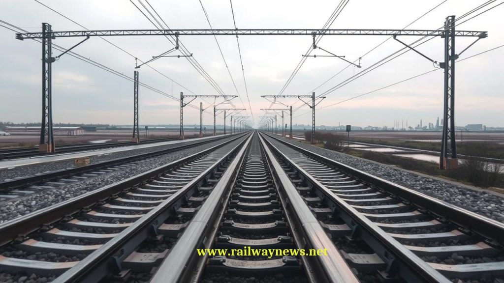
When the first TGV Sud-Est service departed Paris Gare de Lyon for Lyon on 27 September 1981, it was the fastest scheduled passenger train service in the world. At 260 km/h on the newly built LGV Sud-Est, it was also travelling at a speed at which the conventional French lineside signalling system — the three-aspect “crocodile” system — was completely useless. At 260 km/h, a signal mounted beside the track would be past the driver’s window in approximately 1.5 seconds — far too quickly for reliable reading and braking response. The TGV needed a different approach.
The approach that SNCF and Alsthom engineers developed was TVM — Transmission Voie-Machine. Rather than building additional trackside infrastructure or using the wireless radio technology that was not yet mature enough for safety-critical use in the early 1980s, TVM used what was already there: the rails themselves. The electrical pulses that conventional track circuits used to detect trains could also carry information. By encoding speed permissions as specific audio frequencies in those pulses, the signal information that would have been displayed on lineside lights could be transmitted directly to the train’s cab, where it appeared on the driver’s display. No lights beside the track. No radio tower. The rails themselves became the signal.
What Is TVM?
TVM (Transmission Voie-Machine) is a coded track circuit system that performs two functions simultaneously: train detection (the classical track circuit role) and cab signalling (transmitting speed and authority information to the train). It is both the signalling infrastructure and the ATP system on French LGV high-speed lines — and on the UK section of the Channel Tunnel and HS1.
TVM is not the same as a conventional track circuit. A conventional track circuit uses a simple low-frequency DC or AF current that is either present (section clear) or shorted by a train axle (section occupied). TVM uses multiple specific audio-frequency carrier signals, each encoding a different speed permission — the choice of frequency transmitted in each section carries the “message” to the passing train.
How TVM Works: Coded Frequencies in the Rails
| Step | What Happens | Technical Detail |
|---|---|---|
| 1. Frequency selection | The block controller/interlocking determines the appropriate speed code for each section based on occupancy, route setting, and the speed of the preceding train | Speed code → specific frequency combination selected from the TVM code table |
| 2. Rail transmission | The selected audio-frequency current is fed into the rail at the section boundary via a transmitter unit | Frequency flows from transmitter through one rail, across train axles, back through other rail to receiver; insulated joints separate adjacent sections |
| 3. Onboard reception | The train’s receiver coils, mounted under the cab near the leading axle, detect the frequency flowing through the rail | Inductive coupling between coil and rail; same physical principle as conventional track circuit but at audio frequency |
| 4. Frequency decoding | The onboard TVM decoder identifies the received frequency and translates it to a speed permission | Each frequency-modulation combination maps to a specific speed code (e.g., 300, 270, 230, 170, 80 km/h or Stop) |
| 5. Display and supervision | The decoded speed code is displayed on the driver’s cab display; ATP enforces compliance | Speed code displayed numerically; ATP applies service/emergency brake if actual speed exceeds code speed |
| 6. Section entry detection | When the train enters a new section, its axles short the new section’s rail current; the previous section’s frequency is no longer received; the new section’s frequency is now detected | The transition between sections is the moment the driver sees the speed code change on the cab display — the “virtual signal” moment |
TVM 300 vs TVM 430: The Two Generations
| Parameter | TVM 300 | TVM 430 |
|---|---|---|
| Maximum speed | 270 km/h (later upgraded sections to 300) | 320 km/h |
| Speed code resolution | Stepwise: 300/270/230/170/80/000 km/h codes | Higher resolution speed codes; gradient-modified braking curve computation |
| Braking supervision | Step-target: enforce speed code limit at section entry point | Continuous braking curve: supervise against calculated deceleration profile using gradient data |
| Gradient compensation | No — same braking profile regardless of gradient | Yes — braking curve adjusted for uphill/downhill sections |
| Lines equipped | LGV Sud-Est (Paris–Lyon, 1981); LGV Atlantique (Paris–Tours/Le Mans, 1989) | Channel Tunnel (1994); LGV Nord (Paris–Lille–Brussels); LGV Est (Paris–Strasbourg); HS1 (UK) |
| Notable characteristic | Pioneeered cab-only signalling on LGV; first generation | Higher capacity: allows shorter braking margins through gradient awareness; suitable for >300 km/h |
The TVM Cab Display: What the Driver Sees
A TGV driver on an LGV line sees none of the red/yellow/green lineside signals that define the conventional railway experience. Instead, their primary speed information comes from two cab instruments:
The speed code display: A large numeric display showing the current TVM speed code — the permitted speed for the current section. When the train crosses into a new section, this display updates to reflect the new code. The driver must not exceed this value. Common TVM speed codes include 000 (stop required at next block marker), 080, 130, 170, 230, 270, 300, 320 km/h.
The target speed display: A secondary display showing the target speed for the next section — what speed the driver should be at when they cross the upcoming section boundary. This is the “prepare to slow to” instruction, equivalent to the approach caution information that conventional yellow signals provide.
The ATP enforcement system continuously compares the train’s actual speed (from the tachometer) against the permitted speed code. In TVM 300, intervention occurs if the actual speed exceeds the code speed at the section boundary — the driver must be at or below the target speed before entering the new section. In TVM 430, intervention is continuous, with a calculated braking curve that the driver must be within throughout the approach to the restriction.
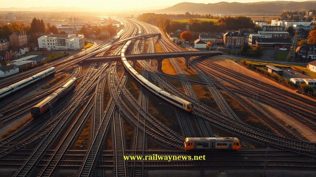
Block Sections on LGV: The JAL Marker System
Although TGV lines have no traditional lineside signal heads, they are not entirely unmarked. Blue boards with yellow chevrons — called JAL (Jalon d’Arrêt de Ligne) or block markers — appear alongside the track at every block section boundary. These serve several functions:
- Visual position reference: A driver receiving a “000” (stop) speed code knows they must bring the train to a standstill at the next JAL marker — it is the physical “signal” to stop before.
- Emergency reference: In the event of TVM failure or communication issues, the JAL markers provide the driver with a physical reference for block boundaries that they can use when operating under degraded mode rules.
- Maintenance reference: Engineers performing track work use JAL positions as section boundary references when requesting possessions from the TVM control system.
The JAL system illustrates an important design principle of LGV operations: the TVM system is the primary authority medium, but the physical infrastructure retains visual reference points that allow operations to continue (at reduced speed) in the event of system degradation.
Multi-System Operation: The Eurostar Challenge
The Eurostar service — operating from London through the Channel Tunnel to Paris and Brussels — presented one of the most complex ATP multi-system challenges in railway history. A single Eurostar set must be capable of operating under four different signalling systems in a single journey:
| Section | Country | Signalling System | Speed |
|---|---|---|---|
| LGV Nord (Paris area) | France | TVM 430 | 300 km/h |
| Conventional line approaches | France | TVM + KVB (conventional) | Up to 220 km/h |
| Channel Tunnel | UK/France | TVM 430 (same as LGV) | 160 km/h in tunnel |
| HS1 (UK high-speed) | UK | TVM 430 + ETCS Level 2 | 300 km/h |
| Classic lines (London approach) | UK | AWS + TPWS (UK conventional) | 160 km/h |
The original Class 373 Eurostar sets were equipped with TVM 430, AWS, TPWS, and TBL (Belgian train protection) in a single vehicle — four ATP systems managed by the onboard computer, which selected the active system based on the detected trackside signals. The transition between systems was largely automatic, triggered by balise groups at system boundary points. This complexity was exactly the kind of operational challenge that ETCS was designed to eliminate.
TVM vs LZB vs ETCS: The European Cab Signalling Family
| Parameter | TVM (France) | LZB (Germany) | ETCS Level 2 (Europe) |
|---|---|---|---|
| Transmission medium | Running rails (coded track circuit) | Dedicated cable loop in track | GSM-R radio + Eurobalise spot |
| Train detection | Intrinsic (same rail circuit) | Separate track circuits alongside loop | Separate (track circuits or axle counters) |
| Trackside infrastructure | Rail transmitters/receivers at section boundaries; no additional cable | Dedicated conductor cable entire route | Eurobalises at key points; radio towers |
| Block type | Fixed block (TVM section = block) | Fixed block with dynamic braking curve | Fixed block (L1/L2); moving block (L3) |
| Max speed | 320 km/h (TVM 430) | 280 km/h (300 tested) | 350+ km/h (no speed limit in spec) |
| Interoperability | France + Channel Tunnel + HS1 (UK) only | Germany + Austria + Spain (AVE) only | Pan-European standard |
| Future | ETCS migration planned for LGV network | ETCS replacement underway ~2030 target | European standard for all new deployments |
TVM’s Legacy: The Influence on ETCS
TVM, like Germany’s LZB, contributed important operational proof to the ETCS specification process. TVM demonstrated that:
- No lineside signals are needed at high speed — the driver can operate safely from cab display information alone, across a complete LGV network, in daily passenger service at 300+ km/h.
- Coded track circuits can carry signalling information — the use of audio frequency rail currents to transmit speed codes directly informed the design of ETCS coded track circuit systems for fixed-block ETCS Level 2 deployments.
- Block-section based speed code transmission is operationally viable — though ETCS moved to radio for its continuous transmission, the TVM experience validated the fixed-block cab signalling concept that Level 1 and Level 2 use.
The ETCS DMI’s information architecture — displaying permitted speed, target speed, and target distance — maps directly onto TVM’s three-value cab display concept. Where TVM showed the speed code for the current section, ETCS shows the continuous braking curve calculation derived from a continuously updated movement authority. The conceptual continuity is direct.
Editor’s Analysis
TVM and LZB are the two national systems that proved European high-speed cab signalling was operationally feasible — and they did so using entirely different physical transmission approaches (rail-coded current versus dedicated cable loop), which is itself instructive. The core capability — continuous cab signalling, automatic speed enforcement, cab display replacing lineside signals — could be achieved by different engineering means, and both approaches worked reliably for decades. This is the strongest possible evidence that the concept was sound, and it gave the ETCS specification process the confidence to adopt continuous cab signalling as the mandatory approach for all future European high-speed lines. The irony is that the commercial success of TVM and LZB — their deployment on major national networks, their accumulation of 40 years of operational evidence, their deep integration into fleet and infrastructure — is precisely what makes their replacement by ETCS so slow and expensive. The trains that carry TVM 430 receivers and the infrastructure that transmits TVM codes represent billions of euros of existing investment that cannot be switched off overnight. The ETCS migration on the LGV network will proceed over two decades, managing the parallel operation of TVM and ETCS across a progressively expanding fleet of dual-equipped trains. The transition will eventually be complete, and the last TVM-equipped LGV section will be upgraded. When that happens, TVM will have operated for over 40 years, carried billions of passengers, and provided the operational proof of concept that made ETCS possible. That is a legacy worth remembering. — Railway News Editorial
Frequently Asked Questions
- Q: Why does TVM use the rails instead of a separate cable or radio?
- TVM’s use of the running rails as its transmission medium was a deliberate engineering choice made in the late 1970s when the LGV design was being finalised. Radio communication technology in the late 1970s was not sufficiently mature or reliable for safety-critical railway applications — the kind of continuous, dependable, low-latency data link required for ATP would not have been achievable with the mobile radio technology available. Dedicated cable loops (as Germany’s LZB used) required significant additional trackside infrastructure and maintenance burden. The rails, by contrast, were already present, already maintained, and already used for conventional track circuit operation. Using audio-frequency coded signals in the same rails extended an existing infrastructure to carry a new function — an elegant engineering choice that minimised new infrastructure requirements. The subsequent development of GSM-R as a reliable railway radio standard in the 1990s made radio the preferred medium for ETCS, but when TVM was designed, the rails were the right answer given the available technology.
- Q: How does TVM handle a situation where a train is stranded in a section?
- A stopped or slow-moving train in a TVM section occupies that section, causing the track circuit to show “occupied.” The TVM control system detects the occupied section and progressively adjusts the speed codes transmitted in upstream sections to slow approaching trains. The code sequence approaching an occupied section would typically be: normal line speed in distant sections → 270 km/h (warning) → 230 km/h → 170 km/h → 080 km/h → 000 (stop before next JAL marker). The approaching TVM-equipped train’s cab display shows these progressively restrictive codes, and the onboard ATP enforces the required braking profile. If the stranded train’s position is known precisely, the stop code (000) is transmitted in the section immediately upstream of the obstruction. The following driver must bring the train to a stop before the next JAL marker and then await instructions from the control centre before proceeding under degraded mode rules.
- Q: Can a conventional (non-TGV) train operate on an LGV?
- Only if equipped with TVM receivers. LGV lines have no conventional lineside signals in their cab-signalling-only sections — a train without TVM (or ETCS where that has been deployed) would have no speed information or ATP protection. Some LGV sections carry dual TVM/conventional signalling to allow non-TVM equipped locomotives to operate at restricted speeds for maintenance and rescue purposes, but passenger operations require TVM equipment. The operational restrictions imposed by the need for TVM-equipped stock is one reason why the LGV network is predominantly operated by dedicated TGV fleet rather than conventional express stock — the cost and complexity of equipping conventional locomotives with TVM is not usually justified for the limited frequency with which they would use LGV sections.
- Q: What is the block section length on a French LGV?
- LGV block sections are significantly longer than those on conventional lines — typically 1,500 to 3,500 metres, with some sections approaching 4,000 metres. This length reflects the braking distance required at TGV speeds: at 320 km/h, a TGV requires approximately 3,200–3,500 metres to stop from full speed. Each block section must be long enough that a train cannot enter a section and fail to stop before the end of that section and the beginning of the next, even under worst-case braking conditions. The long sections mean that the TVM speed code sequence approaching an obstacle spans many kilometres — the transition from full speed to stop may involve 5–7 section transitions, each progressively restricting the approaching train’s speed.
- Q: Is TVM being replaced by ETCS on French LGVs?
- Yes — SNCF Réseau and SNCF have committed to ETCS deployment on the French LGV network, but the migration is gradual. New LGV construction (LGV Sud Europe Atlantique, LGV Bretagne-Pays de la Loire) has included ETCS Level 2 from opening, operating alongside TVM for trains that do not yet carry ETCS onboard equipment. Existing LGVs are progressively being equipped with ETCS infrastructure while retaining TVM in parallel. The fleet migration — equipping each TGV, Eurostar, Thalys/Eurostar high-speed train, and regional TER service that uses LGV paths — will take years. The TVM system will not be switched off until the last non-ETCS-equipped train type that uses LGV sections has been retired or re-equipped. Given rolling stock lifecycles of 30+ years, complete TVM decommissioning on all French LGV sections is likely to extend into the late 2030s or beyond.

Railway infrastructure, rolling stock and transport technologies specialist focused on global rail industry developments, high-speed rail systems, signaling technologies and freight transportation. Covering railway investments, public transport modernization, rail operations and international mobility projects across Europe, Asia and North America.
BENZER KONULAR
July 4, 2026 11:41 pm
Eurostar cancelled all direct London–Amsterdam trains through July 2 after...
July 1, 2026 1:37 pm
NRHS awarded $187K to 34 U.S. rail heritage projects in...
July 1, 2026 1:42 am
UK government launched a £30bn Better Connected plan, allocating £15.6bn...

July 1, 2026 6:37 am
Amtrak launched a small-plate dining program for Acela First Class...
July 1, 2026 8:49 am
The Short Line Training Center launched FRA-funded online DSLE and...
July 4, 2026 11:02 pm
Eurostar suspends all direct London–Dutch trains through 2 July after...