
What is a Eurobalise? The “Yellow Box” Telling Trains Where They Are
Eurobalise: ETCS passive transponder providing absolute position fixes; data transmission. Over 3 million deployed globally, standardised under UNISIG Subset-036/085.
⚡ In Brief
- A Eurobalise is a passive transponder bolted between the rails that communicates with a passing train’s onboard equipment via electromagnetic induction — the train’s antenna powers the balise, and the balise instantly transmits its data telegram in return. No cable connection or battery is required on a fixed-data balise.
- The Eurobalise is the primary position-reference and data-transmission device for ETCS (European Train Control System), serving as both a digital milepost (providing absolute position fixes to correct odometry drift) and a signal-data relay (transmitting movement authorities and speed limits to the train).
- A single Eurobalise telegram transmission takes approximately 1 millisecond — a train passing at 500 km/h crosses a balise in roughly 2 milliseconds, so the entire data exchange is completed in a fraction of the available window.
- Two types of balise serve different functions: fixed-data balises contain permanent data about location and track characteristics; controlled (switchable) balises are connected to a Lineside Electronic Unit (LEU) and transmit real-time signal aspect and movement authority data that changes with signal states.
- Despite the name “Eurobalise,” the technology is used globally — in China, India, Saudi Arabia, Taiwan, and Australia — wherever ETCS or compatible ATP systems are deployed. Over 3 million Eurobalises have been installed worldwide.
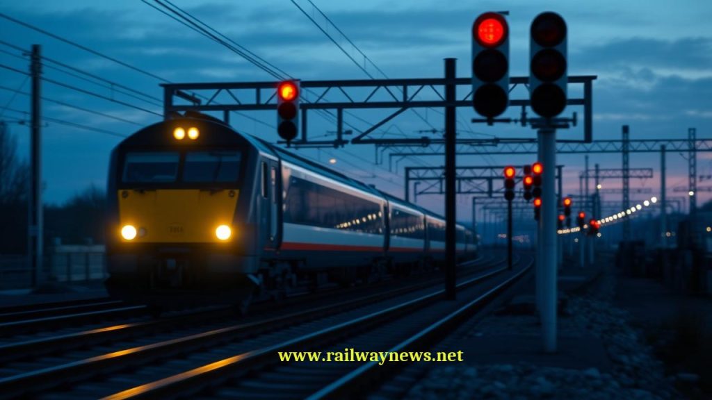
If you lift a floor grating in the middle of a European high-speed track section, or look carefully between the rails at any ETCS-equipped station, you will find a yellow rectangular device approximately 430 mm × 370 mm × 85 mm, bolted to the sleeper between the rails. It has no external wires (unless it is a controlled balise), no visible indicator lights, no display. It sits passively in all weathers — rain, snow, temperatures from −40°C to +85°C — waiting for a train to pass over it.
In the 1–2 milliseconds of the train’s passage, a data exchange occurs that is fundamental to European railway safety: the train’s onboard antenna energises the balise electromagnetically; the balise uses that power to transmit a 1,023-bit data telegram containing the train’s precise location, speed limits, gradient information, or real-time signal state; the onboard ETCS computer processes the telegram and updates the train’s movement authority. The transaction is complete before the balise is 2 metres behind the train. This is the Eurobalise — an object of prosaic appearance and remarkable engineering.
What Is a Eurobalise?
A Eurobalise (standardised under UNISIG Subset-036 and Subset-085, part of the ETCS specification family) is a passive transponder installed between the rails at defined locations along an ETCS-equipped railway. It forms part of the BTM (Balise Transmission Module) system — the interface between the trackside infrastructure and the train’s ETCS onboard unit.
The balise’s primary functions are:
- Absolute position reference: Each balise has a unique identifier and a precisely surveyed position. When the train’s onboard computer detects a balise, it updates the train’s odometry — correcting the accumulated positioning error that builds up between balise locations from wheel-rotation counting.
- Data transmission: The telegram transmitted by a controlled balise can contain ETCS movement authority data, speed profile information, gradient profiles, track description data, and signalling messages from the interlocking system.
How a Eurobalise Works: The Inductive Power and Communication Cycle
| Step | What Happens | Technical Detail |
|---|---|---|
| 1. BTM field emission | The BTM antenna under the locomotive emits a continuous 27.095 MHz electromagnetic field downward | Field is continuous while train is in motion; antenna mounted 235–335 mm above rail head |
| 2. Balise energisation | As the BTM field enters the balise’s coupling area, the 27.095 MHz signal inductively powers the balise electronics | No battery required — all power derived from the BTM field; energisation begins ~500 mm before balise centre |
| 3. Data preparation | Balise electronics retrieve stored telegram (fixed) or current telegram from LEU (controlled) | 1,023-bit telegram; FSK modulation on 4.234 MHz uplink carrier |
| 4. Uplink transmission | Balise transmits telegram to BTM antenna at 4.234 MHz | Transmission takes ~1 ms; train at 500 km/h crosses the coupling zone in ~2 ms — sufficient margin |
| 5. BTM reception | BTM receives telegram and forwards to ETCS onboard unit for decoding | Error checking via CRC; if telegram fails validation, BTM reports reception failure to EVC |
| 6. Position update | ETCS onboard unit (EVC) updates train position to balise’s known chainage; resets odometry error accumulation | Position accuracy immediately after balise: ±10 cm; degrades to ±several metres between balises depending on speed and distance |
Fixed vs Controlled Balises: The Two Types Explained
| Parameter | Fixed Data Balise | Controlled (Switchable) Balise |
|---|---|---|
| External wiring | None — completely standalone | Cable to LEU (Lineside Electronic Unit) |
| Data content | Permanent: position ID, chainage, gradient, permanent speed limit, track description | Dynamic: current signal aspect, movement authority end point, temporary speed restrictions |
| How data changes | Only changed by physical replacement or reprogramming on-site | LEU receives signal state from interlocking and updates balise telegram in real time |
| Primary use | Odometry correction; permanent infrastructure data | ETCS Level 1 movement authority transmission; TSR (Temporary Speed Restriction) notification |
| Fail-safe behaviour | Always transmits same data — no failure modes affecting safety | If LEU connection fails, balise defaults to most restrictive state (danger/stop aspect) |
| Typical deployment density | Every 100–3,000 m depending on odometry needs | At every signal location in ETCS Level 1; every 100–500 m in Level 1 full supervision |
The LEU: The Interface Between Interlocking and Controlled Balise
The Lineside Electronic Unit (LEU) is the electronic device that bridges the interlocking system and a controlled balise. It monitors the signal aspect outputs from the interlocking and translates them into ETCS telegram content that the connected balise transmits to passing trains.
For example, when signal A shows green (clear), the LEU programmes the controlled balise upstream of signal A to transmit a telegram containing the movement authority to pass the signal and the permitted speed. When signal A changes to red, the LEU immediately updates the balise telegram to reflect the danger aspect — the next train to pass the balise receives an authority that limits it to a stop before the signal.
The LEU is a safety-critical device (typically SIL 2 or SIL 3) because a failure that causes a controlled balise to transmit a false “clear” authority would present a safety hazard. LEU design incorporates internal self-monitoring and defaults to the most restrictive output (equivalent to red) if any fault is detected.
Balise Groups: Why Balises Come in Pairs
In ETCS practice, balises are usually deployed in groups of two or more rather than individually. A balise group allows the onboard system to:
- Determine direction of travel: The sequence in which the onboard system reads two balises (A before B, or B before A) tells it which direction the train is moving, enabling correct interpretation of the movement authority data.
- Confirm position: Reading two balises in the expected sequence confirms that the train is at the expected location and moving in the correct direction. A single balise cannot determine direction.
- Provide redundancy: If one balise in a group fails to transmit, the second may succeed. The onboard system can reconstruct sufficient data from a partial group reception.
In standard ETCS Level 1 deployment, a typical balise group at a signal location consists of one controlled balise (carrying the dynamic signal aspect data) and one or more fixed balises (carrying position and infrastructure data).
Balises in ETCS Level 1 vs Level 2
| ETCS Level | Balise Role | Movement Authority Source | Balise Density |
|---|---|---|---|
| Level 1 | Primary authority transmission + position | Controlled balise (via LEU from interlocking) | High — one group at every signal; intermediate position groups |
| Level 2 | Position reference only (odometry correction) | Radio (GSM-R/FRMCS) from RBC | Lower — every 1–5 km for odometry; plus transition points |
| Level 2 transition | Level transition announcement + first position fix | Balise announces entry into L2 area; RBC takes over authority | Mandatory at every Level 1/2 transition point |
In ETCS Level 2, the movement authority is transmitted to the train by radio from the Radio Block Centre (RBC) — not by balises. However, balises remain essential even in Level 2 for two functions: providing absolute position fixes to correct the cumulative error of odometry, and announcing level transitions when a train moves from a Level 1 area into a Level 2 area (or vice versa).
Odometry and Why Trains Need Position Correction
Train position in ETCS is primarily determined by odometry — counting wheel rotations and multiplying by the known wheel circumference to calculate distance travelled from the last known reference point. This method is simple and requires no external communication, but it accumulates errors over distance due to wheel slip, wheelslide, wheel wear (changing effective circumference), and measurement noise.
On an ETCS Level 2 line at 300 km/h with balise groups spaced 5 km apart, the accumulated odometry error between balise fixes can reach ±5–15 metres. This error must be within the safety tolerances of the movement authority — the EVC (European Vital Computer, the ETCS onboard processor) adds this uncertainty to its braking curve calculation, bringing the train to a stop before the end of authority even accounting for the worst-case position error.
When the train crosses a balise group, the EVC snaps the position estimate to the balise’s surveyed location, resetting the accumulated error to near-zero. This is why balise density is a design parameter in ETCS systems — denser balises mean smaller odometry errors, allowing tighter movement authority margins and higher capacity; but denser balises mean more installation and maintenance cost.
Physical Specifications and Installation
| Parameter | Specification |
|---|---|
| Dimensions | Standard: 430 mm × 370 mm × 85 mm |
| Mounting | Bolted to sleeper (concrete or timber) between rails using M16 bolts and cast-in inserts |
| Height above rail | Top surface 80–220 mm below rail head level (under ballast shoulder for buried installations) |
| BTM antenna height | 235–335 mm above rail head (bottom of antenna to rail head) |
| Operating temperature | −40°C to +85°C |
| IP rating | IP68 — fully submersible; unaffected by flooding, snow, ice |
| Design life | 20+ years; resistant to train-induced vibration (EN 50159 environmental class) |
| Uplink frequency | 4.234 MHz (balise to train) |
| Downlink frequency | 27.095 MHz (train to balise — energising field) |
| Maximum train speed | 500 km/h (certified); current highest operational deployment ~350 km/h (TGV) |
Balise Failure Modes and Safety Behaviour
The ETCS system is designed so that balise failures produce safe outcomes:
Missing balise (expected but not received): If the onboard system expects a balise group at a known location (because the previous balise announced the upcoming group) and does not receive it, the EVC treats the missing reception as a potential failure and enters a more conservative supervisory mode — it cannot confirm position has been updated and must use the worst-case odometry error in its calculations. Depending on the specific ETCS implementation and route design, this may result in an automatic speed reduction or brake application.
Corrupted telegram (received but failed error check): If the EVC receives a telegram that fails CRC validation — indicating data corruption during transmission — it discards the telegram and treats the balise as not received. The same conservative response as a missing balise applies.
LEU failure (controlled balise): A controlled balise whose LEU connection has failed defaults to transmitting the most restrictive telegram — equivalent to a stop aspect. This fail-safe behaviour means a LEU failure causes trains to stop rather than proceed, which may cause operational disruption but cannot cause a dangerous false-clear condition.
Editor’s Analysis
The Eurobalise is a quiet masterpiece of railway engineering: a device that performs a safety-critical function reliably across 20+ years in one of the most mechanically hostile environments in civil infrastructure — between the rails, subject to vibration loads from passing trains, flooding, temperature extremes, and chemical contamination from ballast treatments — without any power supply, without any active maintenance, and in a communication window measured in milliseconds. The simplicity of the passive fixed balise is its strength: there is almost nothing to go wrong. The controlled balise is slightly more complex, but the LEU architecture that drives it is well-understood and the fail-safe design means that failures produce restrictive rather than permissive outcomes. What makes the Eurobalise story interesting in 2026 is its relationship to ETCS Level 3. If true moving block requires the elimination of track circuits, and if DAS fibre sensing can eventually replace track circuits for broken rail detection, the role of balises in a Level 3 world becomes strategic: they may remain as odometry correction and level transition devices even in a system that has no fixed blocks and no lineside signals. Alternatively, continuous high-accuracy positioning via FRMCS radio-based ranging or GNSS-augmentation could reduce the required balise density substantially. The balise’s future depends on how the positioning accuracy problem — and the broken rail detection problem — is ultimately solved at the system level. The yellow box between the rails has been fundamental to European rail safety for thirty years; whether it remains so for the next thirty depends on engineering decisions that are still being made. — Railway News Editorial
Frequently Asked Questions
- Q: How can a Eurobalise work without a battery or power cable?
- The Eurobalise uses inductive power transfer — the same principle as a wireless phone charger, but operating at higher power and at a greater distance. The BTM antenna beneath the locomotive emits a 27.095 MHz electromagnetic field continuously while the train is in service. When the train passes over a balise, this field penetrates the balise’s housing (which is transparent to radio frequencies) and couples inductively with the balise’s internal coil. The induced current powers the balise’s electronics — just enough to read the stored data, modulate it onto the 4.234 MHz uplink carrier, and transmit the telegram before the train has passed. The entire power-up and transmission cycle is completed in approximately 1–2 milliseconds. Because the power is available only when a train is passing — and only for the duration of the coupling event — the electronics are designed to power up, operate, and transmit in an extremely short window. The result is a device that is genuinely passive: no battery degradation, no power supply maintenance, no external electrical connection required for a fixed balise.
- Q: What data is actually contained in a Eurobalise telegram?
- A Eurobalise telegram is a 1,023-bit data structure containing a series of ETCS packets. The specific content depends on the balise type and location, but can include: the balise’s National Reporting Value (unique identifier), the Linking Information packet (announcing the location and expected reception of the next balise group), Track Description (gradient profile, track conditions), Speed Profile (permitted speeds in the section ahead), Movement Authority (for ETCS Level 1 controlled balises — the authority to proceed to a defined end point at defined speed), Temporary Speed Restriction (active TSR issued by the infrastructure manager), and Level Transition Order (if the train is about to move from one ETCS level to another). A fixed position balise typically carries only the identifier, linking information, and static infrastructure data. A controlled signal balise carries the dynamic movement authority derived from the current signal aspect via the LEU.
- Q: Can a Eurobalise be read at 500 km/h — isn’t that too fast?
- The Eurobalise standard is certified for operation at up to 500 km/h, and the physics support this. At 500 km/h, a train travels approximately 139 metres per second. The coupling zone between the BTM antenna and the balise — the distance over which the field is strong enough to power and communicate with the balise — is approximately 300–500 mm. The time available for the complete communication cycle is therefore approximately 2–3 milliseconds at 500 km/h. The telegram transmission itself takes approximately 1 millisecond. The remaining time provides margin for the power-up transient and for the BTM’s signal processing. The data rate of the uplink (approximately 565 kbps using FSK modulation) is specifically chosen to complete the 1,023-bit telegram in approximately 1.8 milliseconds — fitting comfortably within the available window even at the maximum certified speed. In practice, the fastest operational railway using Eurobalises is the French LGV network, where TGVs operate at up to 320 km/h in commercial service — well within the certified speed range.
- Q: What happens if someone places metal debris on a Eurobalise?
- The Eurobalise communicates via electromagnetic induction — the magnetic field passes through non-metallic materials (snow, ice, rain, ballast, plastic debris) without significant attenuation. However, metallic objects placed on or very close to the balise can disrupt the electromagnetic coupling in two ways: they can shield the balise from the BTM’s energising field, preventing power-up; or they can reflect and scatter the uplink signal, causing reception errors. A metal plate directly on the balise surface would likely prevent communication entirely. In practice, the balise housing is designed to be flush with or slightly below the ballast surface level, and the area between rails is generally kept clear of metallic debris as part of routine track maintenance. If a balise fails to transmit and the onboard system expected it (because the previous balise announced it), the EVC treats the absence as a fault and applies conservative supervisory measures. The fail-safe response to metallic interference is therefore the same as for any other balise failure mode: the train is not given false-clear information.
- Q: How is a Eurobalise positioned accurately enough to serve as a reliable location reference?
- The position of each Eurobalise is surveyed to high accuracy when it is installed — typically ±50–100 mm in track chainage using surveying-grade GNSS equipment referenced to a national coordinate system. This surveyed position is then programmed into the balise’s identity (National Reporting Value) and also stored in the ETCS onboard track database, which the locomotive carries. When the EVC detects a balise, it matches the received NRV against the expected balise at the current odometry position and updates the position estimate to the surveyed chainage. The accuracy of the position update is therefore limited by the quality of the original survey — which is typically ±100 mm for a well-installed balise on a quality-assured ETCS deployment. This ±100 mm accuracy is far better than the accumulated odometry error the train would have after travelling several kilometres, which justifies the balise’s role as the primary absolute position reference in ETCS systems.

Railway infrastructure, rolling stock and transport technologies specialist focused on global rail industry developments, high-speed rail systems, signaling technologies and freight transportation. Covering railway investments, public transport modernization, rail operations and international mobility projects across Europe, Asia and North America.
RELATED POSTS
June 1, 2026 8:12 am
MTA Metro-North launched procurement for 252 single-level railcars, funded by...

June 1, 2026 9:25 am
Lumo launched its new Stirling-London Euston West Coast Main Line...