
The Iron Grip: Rail Fastening Systems & The Pandrol Clip
Rail fastening systems are the critical link between the rail and the sleeper. Learn how modern elastic clips, like the Pandrol system, ensure track gauge and absorb vibrations.
⚡ In Brief
- A rail fastening system is the complete assembly of components — clip, rail pad, insulator, and anchor — that attaches the rail foot to the sleeper, maintaining correct track gauge while allowing controlled vertical and lateral elasticity to absorb dynamic wheel loads and protect both the rail and the sleeper from fatigue damage.
- The Pandrol e-clip, invented by Per Pande-Rolfsen and commercialised from the 1950s, is the most widely deployed rail fastening worldwide — an omega-shaped spring steel clip that applies a defined downward toe load (typically 9–12 kN per clip) onto the rail foot through spring tension alone, requiring no bolts, nuts, or regular retightening.
- The rail pad — a rubber or polymer composite plate seated between the rail foot and the sleeper top — is the most functionally critical component in the fastening assembly for vibration isolation and noise reduction. Pad stiffness determines how much of the wheel impact energy is absorbed before reaching the sleeper, the ballast, and the surrounding structure.
- Fastening systems must simultaneously perform three apparently conflicting functions: hold the rail firmly enough to resist longitudinal creep and lateral forces; allow enough vertical flexibility to absorb dynamic impact; and provide electrical insulation between rail and sleeper to preserve track circuit signal integrity.
- On slab track (concrete slab instead of ballasted sleepers), fastening systems carry a higher proportion of the total vibration isolation duty — with no ballast to absorb dynamic energy, the pad and clip assembly must do more work, leading to the use of softer, more compliant pads and two-layer fastening systems on urban slab track where ground-borne vibration transmission to buildings is a design constraint.
The Hatfield derailment on 17 October 2000 killed four people and injured 70 when a Great North Eastern Railway Class 91 train derailed at 185 km/h on the East Coast Main Line in Hertfordshire. The cause was rolling contact fatigue — gauge corner cracking of the rail that had propagated to the point where the rail shattered under the passing train. The investigation found that the rail at Hatfield had been known to be defective for months; replacement had been scheduled but not completed in time.
What the Hatfield investigation also established, through the detailed failure analysis of the track structure at the derailment site, was how the fastening system interacts with rail defect propagation: a fastening assembly that does not maintain correct toe load on the rail foot allows the rail to lift fractionally under passing wheel loads, creating tensile stress at the base of existing cracks and accelerating their propagation. Fastenings that have lost their spring tension through clip fatigue or insulator wear do not merely fail to hold the rail down — they actively contribute to the growth of the defects that eventually cause catastrophic failure.
The rail fastening is rarely the headline component in railway engineering discussions. It is the component that most passengers never see and most non-specialists never think about. It is also the component that, if it fails systematically across a route, can turn a manageable rail defect into a derailment.
What Is a Rail Fastening System?
A rail fastening system is the mechanical assembly that connects the rail to the sleeper (or directly to a slab in slab track construction). Its functions are more complex than the simple description “holds the rail down” suggests:
- Vertical restraint: The fastening applies a defined downward force (toe load) onto the rail foot, preventing the rail from lifting under the tensile phase of the dynamic wheel load cycle and under the thermal tensile forces of CWR in cold weather.
- Lateral restraint: The shoulder, insulator, and clip assembly resists lateral movement of the rail under centrifugal forces in curves and the lateral component of wheel-rail contact forces.
- Longitudinal restraint: The toe load creates friction between rail foot and pad, resisting the longitudinal creep forces from traction, braking, and thermal expansion/contraction of CWR.
- Vibration isolation: The rail pad absorbs high-frequency dynamic energy from wheel-rail contact, protecting the sleeper and substructure from impact fatigue.
- Electrical insulation: The insulator components prevent electrical continuity between the rail and the sleeper/mounting hardware, preserving track circuit signal integrity.
- Gauge maintenance: The assembly maintains the correct distance between the two rails (standard gauge: 1,435 mm) within tolerance.
Evolution of Fastening Systems: From Spike to Spring
| Generation | Type | Mechanism | Primary Weakness | Still Used |
|---|---|---|---|---|
| 1st — Cut spike | Dog spike into timber | Friction grip — spike head bears on rail foot; friction holds rail | Loosens under vibration; no toe load; no lateral restraint; creep pulls rail from spike | North American freight on timber ties; secondary lines |
| 2nd — Bolt and fishplate | Bolted fang/chair on timber | Threaded bolt through rail chair; tightened to defined torque | Vibration loosens bolts; requires regular re-tightening; corrosion seizes threads | Legacy jointed track; some secondary lines |
| 3rd — Spring spike | Cranked spring (Lockspike, Fist) | Spring steel bent into hook shape; driven alongside rail foot; spring tension creates toe load | Lower toe load than clip systems; limited lateral restraint | Widely used on timber sleeper lines in some European networks |
| 4th — Elastic clip (e-clip) | Pandrol e-clip; Vossloh W-clip | Omega/W-shaped spring steel; clip toe bears on rail foot; held in cast shoulder in concrete sleeper | Requires sleeper shoulder to be cast precisely; clip fatigue after many million cycles | Dominant system on European mainlines, HSR, metro worldwide |
| 5th — Resilient baseplate | Pandrol VIPA; Vossloh 300-1; Edilon Corkelast | Clip + soft polymer baseplate assembly; entire rail foot floats on elastomer | Higher cost; more components; requires careful installation | Urban slab track, tunnels, bridges — where vibration isolation is primary concern |
The Pandrol e-Clip: Engineering of a Simple Solution
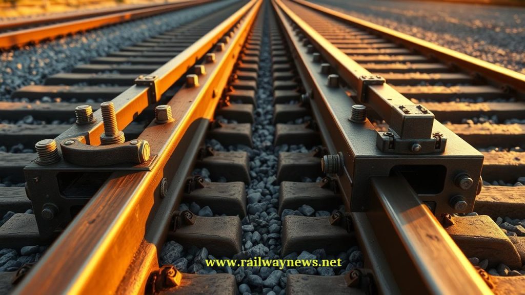
The Pandrol e-clip (originally the Pandrol PR-clip) is a single piece of high-carbon spring steel wire, bent into an omega shape approximately 200 mm long. Its geometry encodes its entire function: the two toe arms bear downward on the rail foot under spring tension; the centre loop provides the spring action; and the two heel arms locate in the cast shoulder of the concrete sleeper, anchoring the clip against the reaction force.
Key engineering properties of the Pandrol e-clip:
- Toe load: 9–12 kN per clip (two clips per rail per sleeper = 18–24 kN per fastening point). This is the downward force exerted on the rail foot by the deflected spring steel.
- Spring deflection: The clip is installed in a pre-stressed state — the toe is forced downward from its natural position to contact the rail foot, creating the design spring tension. This pre-stress is what provides the consistent toe load regardless of vibration.
- Rail lift resistance: The clip resists upward rail movement (dynamic lift) through the same spring force — as the rail lifts, the clip stretches further, maintaining contact and increasing the restraining force.
- No retightening: Unlike bolt-based systems, the spring tension is a material property of the clip steel — it does not reduce under vibration because vibration does not work against spring tension the way it works against bolt friction. This is the “fit and forget” characteristic that made the Pandrol system commercially transformative.
The Pandrol Fastclip: One-Blow Installation
The Pandrol Fastclip (FC) is an evolution of the e-clip design specifically optimised for mechanised installation on high-output track construction and renewal sites. The Fastclip is pre-assembled onto the sleeper at the factory in its “open” (unclipped) position — the clip toes are raised above the rail foot location. When the rail is positioned on the sleeper pads, a single blow from an installation tool rotates the Fastclip toes downward onto the rail foot in one action, completing the fastening.
The operational advantage on a track renewal site is significant: instead of individual e-clips being picked up, positioned, and driven into sleeper shoulders by hand or by semi-automated equipment (a relatively slow process), Fastclip sleepers arrive pre-loaded and are clipped in one pass with a dedicated machine at rates of several hundred sleepers per hour. For major track renewal programmes where the possession window (line closure for engineering) is measured in hours, this installation speed difference directly affects how much track can be renewed per possession — a key economic parameter for network managers.
The Complete Fastening Assembly: All Components and Their Functions
| Component | Material | Function | Failure Mode |
|---|---|---|---|
| Elastic clip | High-carbon spring steel wire (60Si2Mn or similar) | Applies defined toe load to rail foot; provides spring restraint against vertical lift and lateral movement | Fatigue fracture after many million load cycles; corrosion-assisted cracking; toe wear reducing load |
| Rail pad | Rubber (natural or EPDM); polyurethane; EVA composite | Vibration isolation between rail and sleeper; electrical insulation; distributes rail foot pressure across sleeper bearing area | Hardening with age (loss of flexibility); extrusion from under rail foot; splitting; abrasion |
| Insulating shoulder insulator | Glass-fibre reinforced nylon (PA66-GF) | Laterally positions the rail foot at correct gauge; electrically isolates the clip heel from the sleeper/rail; absorbs lateral impact between rail foot and shoulder | Cracking under lateral impact; UV degradation; wear of gauge face; electrical breakdown if cracked |
| Cast shoulder (anchor) | Cast iron (older); ductile iron; steel insert cast into concrete | Anchors clip heel against reaction force; transfers clip toe load to sleeper structure | Shoulder pull-out from concrete (anchor failure); shoulder cracking; corrosion of steel inserts |
| Toe insulator (clip toe cover) | Nylon or HDPE moulding | Electrically isolates the clip toe from the rail foot; prevents galvanic corrosion between spring steel clip and rail steel | Cracking; loss — missing toe insulators are a common track inspection finding requiring prompt replacement |
Rail Pad Stiffness: The Critical Design Variable
Of all the components in the fastening assembly, the rail pad has the most direct influence on track dynamic behaviour and vibration transmission. Pad stiffness — measured in MN/m (meganewtons per metre of deflection) — determines how the wheel load is distributed in time and space as it passes from rail to sleeper:
| Pad Type | Stiffness Range | Dynamic Behaviour | Typical Application |
|---|---|---|---|
| Hard pad | 500–1,000 MN/m | Low deflection; transfers most dynamic load to sleeper; minimal vibration isolation; good longitudinal restraint | Heavy freight ballasted track; track where rail creep is a primary concern |
| Medium pad | 100–500 MN/m | Balanced deflection; moderate vibration isolation; standard compromise for mainline ballasted track | Mainline passenger; mixed traffic on ballasted track |
| Soft pad | 25–100 MN/m | High deflection; good vibration isolation; reduces dynamic forces on sleeper; greater rail bending moment | Concrete slab track; tunnels; bridges; areas with noise/vibration constraints |
| Very soft / isolation pad | <25 MN/m | Very high deflection; maximum vibration isolation; requires special clip system to maintain toe load across large deflection range | Urban slab track in residential areas; near vibration-sensitive buildings (hospitals, concert halls) |
The trade-off in pad selection is between vibration isolation (soft pads are better) and longitudinal restraint (hard pads provide more friction to resist rail creep). On CWR track, insufficient longitudinal restraint can lead to rail creep — gradual displacement of the rail relative to the sleepers that changes the stress distribution and potentially the neutral temperature of the CWR string. On slab track with no ballast to provide additional longitudinal resistance, pad selection must account for this constraint explicitly.
Vossloh Systems: The Main Competitor
Pandrol’s primary competitor in the European and global market is Vossloh (now Vossloh Fastening Systems, part of Vossloh AG). The Vossloh W-clip (and its variants, including the Skl 12, Skl 14, and HM systems) uses a different clip geometry — a W-shaped spring steel plate held by a notched insulator and a ribbed baseplate — but achieves the same fundamental function: defined toe load through spring tension, no retightening required.
The W-clip system is the standard on Deutsche Bahn (DB Netz) and many Central European networks, while the Pandrol e-clip and Fastclip dominate in the UK, French SNCF, many Asian networks, and North American metro systems. Both systems achieve comparable performance; the choice between them is largely a function of network history, existing sleeper shoulder design, and procurement relationships. On new construction, both systems are specified to EN 13481 (Railway applications — Track — Performance requirements for fastening systems).
Fastening Systems on Slab Track
Slab track — concrete slab construction without ballast, used in tunnels, bridges, and urban environments where ballast maintenance is impractical — places different demands on the fastening system. Without ballast to absorb impact energy and provide longitudinal and lateral resistance, the fastening must carry a larger proportion of the dynamic load and provide more of the vibration isolation. The rail pad on slab track is typically softer (lower stiffness) than on ballasted track, and the clip system must maintain consistent toe load over the larger pad deflections this produces.
Two-layer fastening systems — where a clip assembly sits on a resilient baseplate which itself is bonded to the slab — are used in urban environments where ground-borne vibration transmission to adjacent buildings is a design constraint. The two layers of compliance act in series, providing greater total isolation than a single pad could achieve at equivalent stiffness. Systems such as the Pandrol VIPA (Variable Position Anchor), the Vossloh 300-1, and the Edilon Corkelast booted block are examples of this approach, used extensively on metro systems in London, Paris, Amsterdam, and Hong Kong.
Editor’s Analysis
The rail fastening is the component that makes every other track engineering decision work in practice. The most precisely specified rail profile, the most carefully controlled CWR neutral temperature, and the most sophisticated track geometry measurement programme are all undermined if the fastening system is not maintaining its design toe load and gauge position at every sleeper. This is why fastening condition is a standard parameter in track inspection regimes — clip condition, insulator integrity, and pad extrusion are assessed on every inspection pass, and missing or damaged clips trigger a maintenance response before the track geometry deteriorates to a trigger level. The Pandrol e-clip’s “fit and forget” claim is genuine in the sense that it does not require periodic retightening — but it does not mean the clips can be ignored. Spring fatigue, corrosion, and physical damage all progressively reduce toe load below the design value, and the first sign of a developing fastening problem is often a track geometry deterioration rate that is higher than expected rather than any visible failure. The shift toward mechanised track inspection and data-driven maintenance scheduling, with fastening condition assessed by machine vision cameras on measurement trains rather than manual inspection, is making it possible to detect developing fastening deterioration much earlier than was possible with periodic manual inspections. This is an area where the investment in monitoring technology has a direct return in reduced track renewal cost and improved track geometry stability. — Railway News Editorial
Frequently Asked Questions
- Q: Why do concrete sleepers need a special shoulder for the Pandrol clip, while timber sleepers don’t?
- The Pandrol e-clip’s heel arms anchor in a cast shoulder — a rigid protrusion that holds the clip in its pre-stressed position against the reaction force when the clip toes bear on the rail foot. In a concrete sleeper, this shoulder is cast into the sleeper as a steel or ductile iron insert during manufacturing. In a timber sleeper, the traditional fastening approach used screw spikes or coach screws that threaded into the timber, or spring clips (such as the Lockspike) that were driven alongside the rail foot into the timber. The timber provided its own anchor through wood fibre grip. The Pandrol e-clip can be used on timber sleepers with a separate anchor plate (a steel baseplate bolted to the timber that provides the shoulder geometry), but this adds cost and complexity, which is why the e-clip system became the dominant solution on concrete sleeper track rather than as a timber sleeper product. The shift to concrete sleepers in new construction and track renewal from the 1960s onward was closely associated with the shift to elastic clip fastening — the two technologies complemented each other and were often specified together.
- Q: What is “toe load” and why does it matter?
- Toe load is the downward force that the clip toe exerts on the rail foot — the clamping force that holds the rail against the rail pad and sleeper. It is the primary measure of a fastening’s effectiveness: insufficient toe load means the rail can lift under dynamic wheel loading, allowing the rail to vibrate against the pad, increasing stress at existing defect sites, and reducing the friction available to resist longitudinal creep. The design toe load for a Pandrol e-clip is typically 9–12 kN per clip toe — this is achieved by the specific pre-stress deflection applied when the clip is installed in its shoulder. As the clip ages, spring fatigue may reduce this force below the design minimum. A clip with toe load below approximately 6–7 kN is considered to have failed its function and requires replacement. Toe load can be measured non-destructively using a calibrated load cell inserted under the clip toe — this is the standard method for testing clip condition on suspect fastenings. Most network inspection regimes specify a minimum clip toe load threshold below which replacement is mandatory.
- Q: How do rail fastenings affect track circuit performance?
- Rail fastenings must maintain electrical insulation between the rail and the sleeper to preserve the integrity of track circuit signal systems. Track circuits rely on the electrical resistance between the two rails — if current can flow from one rail through a fastening component to the other rail (via the sleeper’s moisture path), it creates a false short-circuit that may indicate “track occupied” when no train is present. The insulator components in the fastening assembly — shoulder insulators, toe insulators, and the rail pad itself — all contribute to the total rail-to-ground resistance. Cracked or missing insulators, contaminated rail pads (where conducting debris bridges the insulation), and deteriorated pads with reduced resistance create paths for leakage current. This is why missing toe insulators are a specific inspection trigger — not because the fastening immediately fails to hold the rail, but because the track circuit insulation is compromised. On track circuit failure modes, fastening insulation degradation is among the most common causes of spurious “occupied” indications that require expensive and disruptive investigation.
- Q: Can fastening systems be monitored remotely or automatically?
- Yes — and this is an active area of development in railway infrastructure management. Several approaches are being deployed commercially. Machine vision systems on track measurement trains use cameras to photograph every sleeper at track inspection speed, with AI image analysis detecting missing clips, displaced insulators, extruded pads, and other visible fastening defects. Acoustic monitoring systems use trackside microphones or distributed acoustic sensing along the track to detect the characteristic sound signature of a loose or missing clip under train passage — a loose clip produces a different acoustic response than a correctly loaded one. Some networks use ultrasonic bolt-through measurement on baseplate systems to verify clip installation torque without manual checking. The shift toward automated fastening inspection is driven by the limitations of manual inspection — the human eye on a walking inspection is reasonably good at finding obviously missing or broken components, but is less reliable at detecting gradually deteriorating toe load or early-stage insulator cracking. Automated systems can inspect every sleeper on every measurement run at line speed, providing a complete dataset that enables data-driven maintenance prioritisation rather than time-based inspection intervals.
- Q: What happens when a rail fastening fails completely?
- A single missing or failed clip at one sleeper is not immediately dangerous — the rail spans across the gap using its own bending stiffness, with the load distributed to adjacent fastenings. Track maintenance rules specify how many consecutive or closely spaced fastening failures are tolerable before a speed restriction is imposed — typically two or three consecutive missing or broken clips within a defined length trigger a speed restriction, and a larger number trigger line closure. The accumulation of fastening failures over a section of track is more serious than a single isolated failure: a section with many degraded fastenings has reduced longitudinal restraint (increasing CWR creep risk), reduced lateral restraint (increasing buckle risk in high compressive stress conditions), and increased dynamic rail movement (accelerating defect propagation). The Hatfield accident was not caused by fastening failure alone, but the contribution of the fastening condition to the rate of gauge corner crack propagation at the defect site was part of the post-accident analysis. This is why systematic fastening deterioration — as opposed to isolated failures — is treated as a priority maintenance issue even when no individual failure has reached a “dangerous” classification.

Railway infrastructure, rolling stock and transport technologies specialist focused on global rail industry developments, high-speed rail systems, signaling technologies and freight transportation. Covering railway investments, public transport modernization, rail operations and international mobility projects across Europe, Asia and North America.
RELATED POSTS
July 4, 2026 11:41 pm
Eurostar cancelled all direct London–Amsterdam trains through July 2 after...
July 1, 2026 1:37 pm
NRHS awarded $187K to 34 U.S. rail heritage projects in...
July 1, 2026 1:42 am
UK government launched a £30bn Better Connected plan, allocating £15.6bn...
July 1, 2026 6:37 am
Amtrak launched a small-plate dining program for Acela First Class...
July 1, 2026 8:49 am
The Short Line Training Center launched FRA-funded online DSLE and...
July 4, 2026 11:02 pm
Eurostar suspends all direct London–Dutch trains through 2 July after...