
Ontario Line: Queen Station Excavation Begins in Toronto
Toronto’s Ontario Line gets a boost! Excavation at Queen Station begins, creating a vital transit hub with seamless integration.
⚡ In Brief
- Queen Station excavation for the Ontario Line reaches 40 m below grade, requiring sequential excavation methods (SEM) and real-time settlement monitoring to protect heritage structures in Toronto’s dense financial district.
- The new Metrolinx platform will integrate vertically beneath the existing TTC Line 1 station, demanding precision underpinning, vibration isolation bearings, and 3D BIM clash detection to avoid utility conflicts.
- Tunnel boring machines (TBMs) for the Ontario Line are 6.8 m diameter, slurry-type units designed for Toronto’s glacial till and Queenston shale, with face pressure control to limit surface settlement to <25 mm.
- Operational target: 38,000 passengers/hour/direction at 90-second headways using automated 5-car trains, exceeding current TTC Line 1 capacity by ~40% while reducing energy use per passenger-km by 30%.
- Full project delivery uses a progressive design-build model with risk-sharing clauses, targeting substantial completion in 2030–2031 at a total capital cost of CAD $10.9 billion (incl. rolling stock and systems).
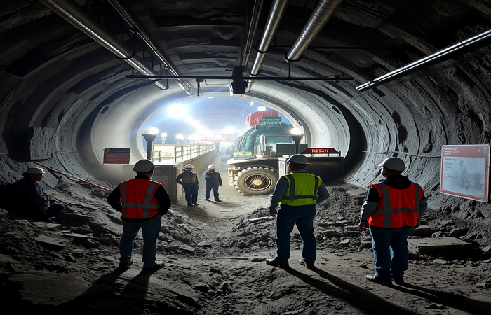
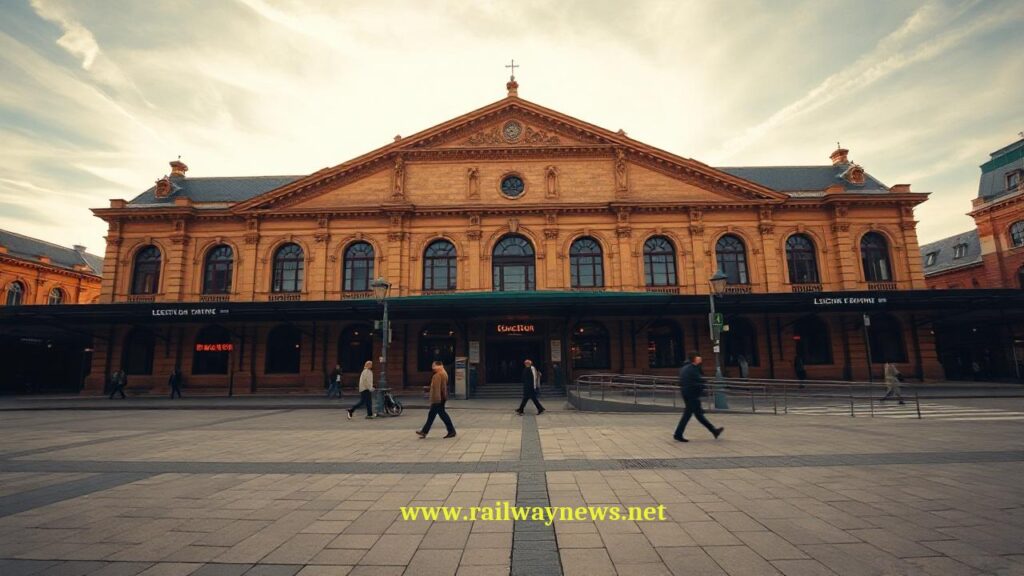
Beneath the bustling intersection of Queen Street West and Yonge Street, where streetcars clang and pedestrians flow in every direction, a transformation is underway that will redefine Toronto’s underground mobility for generations. As excavation crews begin removing the first tonnes of glacial till and Queenston shale for the new Ontario Line platform at Queen Station, the project marks more than a construction milestone—it represents a critical test of urban tunneling ethics, engineering precision, and transit-oriented development philosophy. The Ontario Line, a 15.6 km automated rapid transit corridor from Exhibition Place to the Ontario Science Centre, positions Queen Station as its operational and symbolic heart: the deepest, busiest, and most complex interchange in the network. This article examines the technical architecture of that ambition—how a 40-meter-deep station is engineered in a live urban corridor, how vertical integration with legacy infrastructure is achieved without service disruption, and what global precedents inform the choices being made beneath Toronto’s streets.
What Is the Ontario Line?
The Ontario Line is a fully automated, grade-separated rapid transit line under construction in Toronto, Canada, designed to augment the existing Toronto Transit Commission (TTC) subway network with higher frequency, greater capacity, and improved resilience. Unlike conventional heavy-rail subways, the Ontario Line employs a light-metro profile: 5-car trains (approximately 90 m length) operating on 1,435 mm standard gauge track, powered by 750 V DC third rail, and controlled by communications-based train control (CBTC) with moving-block signaling. The line’s alignment prioritizes direct connections to employment centers, post-secondary institutions, and existing transit nodes, with 15 stations spaced at an average of 1.1 km. Crucially, the Ontario Line is not merely an extension but a parallel capacity corridor: by diverting demand from the congested Line 1 Yonge-University spine, it enables system-wide reliability improvements. From an engineering standpoint, the project is defined by three constraints: (1) minimal surface disruption in a dense, heritage-rich urban core; (2) interoperability with legacy TTC infrastructure at interchange stations; and (3) lifecycle performance targets aligned with Toronto’s 2050 net-zero carbon goals.
Deep Excavation Engineering at Queen Station
Excavating a station box 40 meters below street level in downtown Toronto is not simply a matter of digging a large hole. The geotechnical profile beneath Queen Street consists of three distinct strata: (1) 8–12 m of anthropogenic fill and glacial till (dense, heterogeneous, with boulders); (2) 15–20 m of Queenston shale (weak rock, prone to slaking when exposed to air/water); and (3) bedrock (Lockport dolostone) at approximately 45 m depth. This stratigraphy dictates a hybrid excavation approach: top-down construction for the upper 20 m using secant pile walls and temporary steel struts, transitioning to sequential excavation method (SEM) with shotcrete lining for the lower cavern. Settlement control is paramount. The predictive model for maximum surface settlement (Smax) follows the Peck formula adapted for urban tunnels:
S_max = (V_loss × D) / (2.5 × i)
where V_loss = ground loss ratio (target: ≤0.5%), D = tunnel diameter (6.8 m), i = trough width parameter (function of depth and soil stiffness)
where V_loss = ground loss ratio (target: ≤0.5%), D = tunnel diameter (6.8 m), i = trough width parameter (function of depth and soil stiffness)
For Queen Station, real-time monitoring includes 120+ inclinometers, piezometers, and prism targets linked to a cloud-based dashboard. If settlement rates exceed 2 mm/day or cumulative movement approaches 15 mm, excavation pauses and grout injection is triggered. This protocol draws directly from lessons learned during London’s Crossrail project, where Bond Street station excavation required similar precision to protect adjacent Victorian buildings.
Tunnel Boring & Ground Support Methods
The Ontario Line’s running tunnels are driven by two 6.8 m diameter slurry TBMs, custom-designed for Toronto’s mixed-face conditions. Key specifications include:
| Parameter | Specification | Engineering Rationale |
|---|---|---|
| Cutterhead Type | Mixed-face, 45% disc cutters / 55% scrapers | Optimized for transition from till (abrasive) to shale (fracturable) |
| Face Support | Slurry pressure, 0.8–1.2 bar adjustable | Maintains equilibrium with in-situ earth/water pressure to prevent blowouts |
| Segment Lining | Reinforced concrete, 300 mm thick, gasketed joints | Provides watertightness (<1 L/m²/day) and structural capacity for 100-year design life |
| Grouting System | Two-component (cement + silicate) synchronous grout | Fills annular gap immediately behind TBM to minimize ground relaxation |
| Navigation | Gyro-theodolite + laser guidance, ±15 mm tolerance | Ensures alignment accuracy for CBTC antenna placement and platform screen doors |
| Muck Removal | Slurry pipeline to surface separation plant | Reduces truck traffic in downtown; enables real-time volume monitoring for ground loss calculation |
Significantly, the TBM drive beneath Queen Station includes a “pilot tunnel” phase: a 3 m diameter probe tunnel is advanced first to verify ground conditions and install pre-grouting if water inflow risk is detected. This two-pass approach, pioneered on Singapore’s Downtown Line, reduces the probability of unexpected face collapse by an order of magnitude.
Station Integration & Interchange Design
Queen Station’s vertical integration with the existing TTC Line 1 platform (at ~20 m depth) creates one of North America’s most complex multi-level interchanges. The design challenge is threefold: (1) structural—how to excavate beneath an active station without inducing differential settlement; (2) operational—how to maintain TTC service during 6+ years of construction; and (3) passenger experience—how to enable intuitive, accessible transfers between lines with different fare systems and platform configurations. The solution employs a “floating slab” concept for the new Ontario Line platform: a 1.2 m thick reinforced concrete slab isolated from the surrounding rock by neoprene bearings and steel springs, reducing structure-borne vibration transmission to the TTC level by ≥25 dB. Passenger circulation is modeled using agent-based simulation (software: MassMotion), optimizing stair/escalator placement to achieve a Level of Service (LOS) C or better during peak 15-minute intervals. Critical metrics include:
Flow capacity: Q = n × W × V × k
where n = number of channels, W = effective width (m), V = walking speed (1.2 m/s typical), k = reduction factor for turns/obstacles (0.7–0.9)
where n = number of channels, W = effective width (m), V = walking speed (1.2 m/s typical), k = reduction factor for turns/obstacles (0.7–0.9)
For Queen Station, the design targets a minimum effective width of 2.4 m for all primary corridors, ensuring that even at 38,000 pphpd demand, queue lengths remain under 3 minutes. Fare integration is addressed via a “proof-of-payment” zone in the mezzanine, allowing TTC and Ontario Line users to transfer without passing through additional gates—a policy decision informed by passenger behavior studies on London’s Elizabeth Line.
Ontario Line vs. Global Urban Metro Benchmarks
| Parameter | Ontario Line (Toronto) | Crossrail (London) | Second Ave Subway (NYC) | Downtown Line (Singapore) | Grand Paris Express | TTC Line 1 (Existing) |
|---|---|---|---|---|---|---|
| Line Length (km) | 15.6 | 118 (core: 42) | 13.9 (Phase 1) | 42 | 200 (network) | 38.8 |
| Avg. Station Depth (m) | 28 (Queen: 40) | 32 (Bond St: 45) | 22 | 35 | 30 | 18 |
| Train Capacity (pphpd) | 38,000 | 40,000 | 26,000 | 40,000 | 40,000 | 28,000 |
| Automation Level | GoA4 (Unattended) | GoA2 (ATO with driver) | GoA1 (Manual) | GoA4 | GoA4 | GoA1 |
| Min. Headway (sec) | 90 | 120 | 150 | 90 | 90 | 120 |
| Power Supply | 750 V DC third rail | 25 kV AC overhead | 625 V DC third rail | 750 V DC third rail | 1,500 V DC overhead | 600 V DC third rail |
| Project Delivery Model | Progressive Design-Build | Alliance Contracting | Design-Bid-Build | Design-Build | Public-Private Partnership | Traditional Public Works |
| Target Opening | 2030–2031 | 2022 (core) | 2017 (Phase 1) | 2017 (full) | 2025–2030 (phased) | 1954 (original) |
Safety, Ventilation & Emergency Egress at Depth
Operating a station 40 meters below grade introduces unique life-safety challenges governed by NFPA 130 (Standard for Fixed Guideway Transit and Passenger Rail Systems) and Ontario Building Code Supplementary Standard SB-4. The critical design parameter is evacuation time: all passengers must reach a “place of safety” (typically street level or an adjacent tunnel) within 6 minutes of incident detection. For Queen Station, this is achieved through a layered strategy: (1) redundant egress paths—four stairwells, two escalators (reversible), and one emergency lift per platform end; (2) pressurized escape routes to prevent smoke ingress, with airflow calculated as:
Q_vent = (A_escape × V_min) / η
where A_escape = cross-sectional area of escape route (m²), V_min = minimum air velocity (1.5 m/s to resist smoke backlayering), η = system efficiency factor (0.85 for duct losses)
where A_escape = cross-sectional area of escape route (m²), V_min = minimum air velocity (1.5 m/s to resist smoke backlayering), η = system efficiency factor (0.85 for duct losses)
(3) real-time wayfinding: photoluminescent striping, dynamic signage linked to fire alarm zones, and audible beaconing for visually impaired passengers. Ventilation capacity is sized for a “design fire” of 20 MW (representing a fully involved train car), requiring 120 m³/s of extract airflow. This is delivered by four axial fans (two per end) housed in surface ventilation shafts, with acoustic lining to meet Toronto’s <45 dBA nighttime noise ordinance. Importantly, the emergency lift is not a standard elevator: it features a fire-rated hoistway, backup power with 90-minute autonomy, and a “firefighter override” control panel compliant with CSA B44.1. These specifications were stress-tested using computational fluid dynamics (CFD) simulations in FDS+Evac, modeling smoke propagation and pedestrian movement under worst-case scenarios (e.g., fire at mid-platform with one egress path blocked).
Real-World Precedents Informing Queen Station
Toronto’s engineers have deliberately studied global projects to de-risk Queen Station’s delivery:
- Crossrail Bond Street Station (London, 2012–2022): Excavated at 45 m depth beneath Oxford Street using top-down construction with 1.2 m diaphragm walls. Key lesson: pre-construction 3D laser scanning of adjacent building foundations enabled millimeter-accurate settlement attribution, reducing dispute claims by 70%. Ontario Line adopts this via its “Digital Twin” BIM protocol.
- Singapore Downtown Line Stage 2 (2015): Featured deep stations in soft marine clay. Innovation: jet-grouted “umbrella” arches above excavation to create a self-supporting ground arch, reducing strut loads by 40%. Queen Station applies this concept in its SEM lower cavern.
- NYC Second Avenue Subway Phase 1 (2007–2017): Demonstrated the cost of utility relocation delays. Ontario Line mitigates this via early “subsurface utility engineering” (SUE) surveys to QL-A standard (precise location via vacuum excavation), mapping 120+ utilities before TBM launch.
- Historical Context: Toronto’s Own Legacy: The original Yonge subway (opened 1954) used cut-and-cover at shallow depth (<10 m), causing significant surface disruption. Queen Station’s deep-bore approach reflects 70 years of urban tunneling evolution—prioritizing long-term community benefit over short-term construction convenience.
The excavation beginning at Queen Station is more than a technical milestone; it is a referendum on how cities balance growth with livability. Toronto has chosen a high-capital, high-precision path: investing in deep tunneling to preserve surface character, automating operations to maximize throughput, and integrating vertically to multiply network effects. Yet this ambition carries inherent tensions. The progressive design-build model, while flexible, transfers significant geotechnical risk to contractors—potentially inflating contingency costs if ground conditions prove worse than models predict. The 40-meter depth, while minimizing surface disruption, escalates emergency egress complexity and lifecycle maintenance costs (e.g., elevator reliability becomes a critical availability factor). Most critically, the Ontario Line’s success hinges not on engineering alone but on policy coherence: will fare integration, land-use planning, and last-mile connectivity evolve in tandem? History offers cautionary tales—London’s Crossrail succeeded because it was paired with aggressive density bonuses around stations; conversely, NYC’s Second Avenue Subway, while transformative, remains a “spine without ribs” due to limited feeder bus reforms. Toronto stands at a similar inflection point. If Queen Station becomes a catalyst for transit-oriented development that prioritizes affordability and accessibility, the Ontario Line could redefine North American urbanism. If not, it risks becoming a world-class tunnel serving a fragmented system. The engineering is world-class; the governance must now match it.
— Railway News Editorial
Frequently Asked Questions
1. How does excavation at 40 m depth affect surface buildings in dense downtown Toronto?
Excavation-induced ground movement is the primary risk to surface structures. At Queen Station, the mitigation strategy is multi-layered. First, pre-construction condition surveys document every building within the 45° influence zone (approximately 80 m radius) using 3D laser scanning and crack monitoring gauges. Second, the excavation sequence employs “stiff” support systems: secant pile walls (1.0 m diameter, overlapping by 150 mm) with temporary steel struts at 3 m vertical spacing for the upper 20 m, transitioning to shotcrete-lined SEM with systematic rock bolts (3 m length, 1.2 m spacing) in the lower shale. Third, real-time monitoring triggers adaptive responses: if inclinometer data shows wall deflection exceeding 0.2% of excavation depth, additional ground freezing or compensation grouting is deployed. The target is to limit differential settlement between adjacent building foundations to <1:500 (per CSA S6), preventing structural damage. Crucially, the project uses a “settlement budget” approach: total allowable movement is allocated across construction phases, with 50% reserved for unforeseen events. This methodology, validated on Crossrail, has kept damage claims below 0.1% of project value in comparable projects. For heritage structures like the nearby Elgin and Winter Garden Theatres, additional measures include underpinning with micropiles and temporary load-transfer frames during critical excavation stages.
2. What tunneling method was selected for the Ontario Line and why?
The Ontario Line uses slurry-type tunnel boring machines (TBMs) for the running tunnels, supplemented by sequential excavation method (SEM) for station caverns. This hybrid selection reflects Toronto’s specific geotechnical and urban constraints. Slurry TBMs were chosen over earth-pressure-balance (EPB) machines because Toronto’s Queenston shale, while weak, is prone to clogging in EPB screw conveyors when mixed with clayey till. The slurry system maintains face stability via adjustable bentonite pressure (0.8–1.2 bar), which can be fine-tuned in real-time based on piezometer data. Additionally, slurry transport allows continuous muck removal via pipeline to a surface separation plant, reducing truck traffic in downtown—a critical social license consideration. For station boxes, SEM (also known as the New Austrian Tunnelling Method) is preferred over top-down construction for the lower caverns because it allows flexible adaptation to ground conditions encountered during excavation. Shotcrete lining with steel fiber reinforcement provides immediate support, while systematic instrumentation (convergence tapes, extensometers) informs the “observational method”: if deformation rates exceed predictions, additional support (e.g., invert struts, face dowels) is installed. This approach, pioneered in the Alps and refined on Singapore’s Downtown Line, balances risk and flexibility. Significantly, the TBM design includes a “mixed-face” cutterhead with interchangeable disc cutters (for rock) and scrapers (for soil), allowing rapid adaptation if the tunnel encounters unexpected boulders or water-bearing fractures—a lesson from the 2018 Seattle SR-99 tunneling delays.
3. How will Queen Station handle emergency evacuation from 40 m depth?
Emergency egress from deep stations is governed by the “6-minute rule” in NFPA 130: all occupants must reach a place of safety within six minutes of incident detection. Queen Station achieves this through redundancy, capacity, and intelligence. Redundancy: four independent egress paths per platform (two stairwells, one escalator shaft, one emergency lift), each with fire-rated enclosures (2-hour rating) and positive pressure ventilation to resist smoke ingress. Capacity: stair widths are sized using pedestrian flow modeling to ensure evacuation time remains under 4 minutes even at 100% platform occupancy (approximately 1,200 passengers). The formula for stair flow is Q = 0.8 × W × V, where W is effective width (m) and V is descent speed (0.6 m/s for emergency conditions); Queen Station’s 2.4 m stairs yield ~1.15 persons/second flow. Intelligence: dynamic wayfinding systems use real-time fire alarm data to direct passengers away from affected zones via LED signage and audible beacons. The emergency lift is a critical component: unlike standard elevators, it features a fire-protected hoistway, backup power with 90-minute autonomy, and a dedicated firefighter control panel. Importantly, evacuation drills are simulated annually using agent-based modeling (MassMotion) to identify bottlenecks; recent updates include provisions for passengers with reduced mobility, ensuring evacuation times remain compliant even with diverse user needs. These protocols were stress-tested during the design phase using CFD simulations in FDS+Evac, modeling smoke propagation under worst-case scenarios (e.g., fire at mid-platform with one egress path blocked).
4. What makes the Ontario Line’s automation system different from existing TTC lines?
The Ontario Line operates at Grade of Automation 4 (GoA4), meaning fully unattended train operation (UTO), whereas TTC Line 1 uses GoA1 (manual operation with automatic train protection). The technical distinction lies in the signaling architecture: Ontario Line employs communications-based train control (CBTC) with moving-block principles, while Line 1 uses fixed-block track circuits. In CBTC, trains continuously report position, speed, and direction to a central wayside controller via wireless radio (IEEE 802.11p), which calculates a dynamic “movement authority” envelope for each train. This enables 90-second headways versus Line 1’s 120-second minimum. Crucially, GoA4 requires redundant safety systems: the Ontario Line uses a 2oo3 (two-out-of-three) voting architecture for vital functions, where three independent processors compute braking commands, and a majority vote determines action. This achieves a Safety Integrity Level 4 (SIL 4) target, with a hazardous failure rate <10⁻⁹ per hour per IEC 61508. Additionally, platform screen doors (PSDs) are interlocked with train position via fiber-optic loops, preventing door opening unless the train is precisely aligned (±250 mm tolerance). Cybersecurity is integral: the CBTC network is air-gapped from public networks, with intrusion detection systems monitoring for anomalous commands. These capabilities enable operational benefits beyond frequency: energy optimization via coasting control, predictive maintenance via onboard diagnostics, and resilience via automatic train recovery after disruptions. However, GoA4 also demands rigorous validation: the Ontario Line’s system underwent 10,000+ hours of hardware-in-the-loop testing before revenue service, simulating fault scenarios from wheel slip to communication loss.
5. How does the project mitigate groundwater intrusion in Toronto’s geology?
Groundwater control is critical in Toronto’s stratigraphy, where the water table sits at ~10 m depth and Queenston shale contains fracture networks that can channel flow. The Ontario Line employs a “defense-in-depth” strategy. Primary defense: the TBM segmental lining uses EPDM gaskets rated for 3 bar hydrostatic pressure, with bolted joints torqued to 450 Nm to ensure compression. Secondary defense: synchronous grouting fills the annular gap behind segments with a two-component mix (cement + silicate) that sets within 30 seconds, creating a watertight shell. Tertiary defense: for station excavations, jet grouting creates a “cut-off wall” around the perimeter, with columns overlapping by 200 mm to achieve <10⁻⁹ m/s permeability. Monitoring is continuous: piezometers installed at 5 m intervals measure pore pressure, triggering dewatering wells if levels rise unexpectedly. Crucially, the project avoids aggressive dewatering that could cause regional settlement; instead, it uses “controlled drainage” via sump pumps with sediment filters to meet Toronto’s <25 mg/L turbidity discharge limit. For the Queen Station cavern, a “drainage composite” (geonet + geotextile) is installed behind the shotcrete lining to channel any seepage to collection drains, preventing hydrostatic buildup. This approach draws from London Crossrail’s experience, where unexpected water inflows in the Lambeth Group clays required emergency grouting campaigns. Ontario Line’s geotechnical baseline report includes probabilistic inflow modeling (using MODFLOW), ensuring contingency resources are pre-positioned. Finally, all groundwater discharged is treated via pH adjustment and filtration before release to the municipal storm system, aligning with Toronto’s Green Standard requirements.

Railway infrastructure, rolling stock and transport technologies specialist focused on global rail industry developments, high-speed rail systems, signaling technologies and freight transportation. Covering railway investments, public transport modernization, rail operations and international mobility projects across Europe, Asia and North America.
RELATED POSTS

August 1, 2026 7:56 am
BMZ delivered two new TEM18DM diesel shunting locos to RZD...
August 1, 2026 7:14 pm
€205 billion funding shortfall threatens the TEN-T rail network's completion...
August 1, 2026 7:11 pm
An Ipsos survey across 29 countries found that 33% of...
August 1, 2026 8:06 pm
European Commission approved a regulation on 9 July 2026 requiring...
August 1, 2026 5:11 pm
Italo launched a Rolling Stones campaign on 1 July, running...
August 1, 2026 9:10 pm
Leicester station secured £27.5 million in Levelling Up funding in...